Ultra low pressure drop flow sensor

a flow sensor and ultra-low pressure technology, applied in the field of sensing devices and methods, can solve problems such as unsatisfactory medical ventilator applications

Inactive Publication Date: 2008-03-18
HONEYWELL INT INC
View PDF36 Cites 36 Cited by
  • Summary
  • Abstract
  • Description
  • Claims
  • Application Information

AI Technical Summary

Benefits of technology

[0013]In accordance with an alternative embodiment, a flow straightener can be associated with the flow channel, wherein the flow straightener promotes a bi-directional flow of fluid through the flow channel. The flow straightener can be provided as a restrictor in the shape of a narrow, elongated protrusion that prevents flow eddies, which create pressure instability.
[0014]Sensing fluid velocity in one direction can be accomplished by orienting upstream tap(s) to face into the direction of the gas flow and a downstream tap(s) to face perpendicular to gas flow. The upstream tap senses stagnation pressure of the gas (i.e., the impact as the gas comes to a stop) and the down stream tap senses static pressure which is exerted in all directions in the flow channel. The difference between the pressures is the velocity pressure which drives flow through a bypass channel to a flow sensor. A Pitot tube, for example is based on this phenomena. Historically, though, a pitot tube generates such small pressure drop, it was traditionally used with an incline manometer which is not easily incorporated into electronic circuitry for efficient measurement. Using a flow sensor or ultra low pressure sensor, the velocity pressure can be sensed electronically. In addition, this technique of sensing velocity pressure eliminates the need to add pressure drop to the system to measure flow.

Problems solved by technology

Although only a small pressure drop in the range of 2 in H2O is added to the system, it is undesirable in medical ventilator applications.

Method used


Image

  • Ultra low pressure drop flow sensor
  • Ultra low pressure drop flow sensor
  • Ultra low pressure drop flow sensor

Examples


Embodiment Construction

[0024]The particular values and configurations discussed in these non-limiting examples can be varied and are cited merely to illustrate at least one embodiment and are not intended to limit the scope thereof.

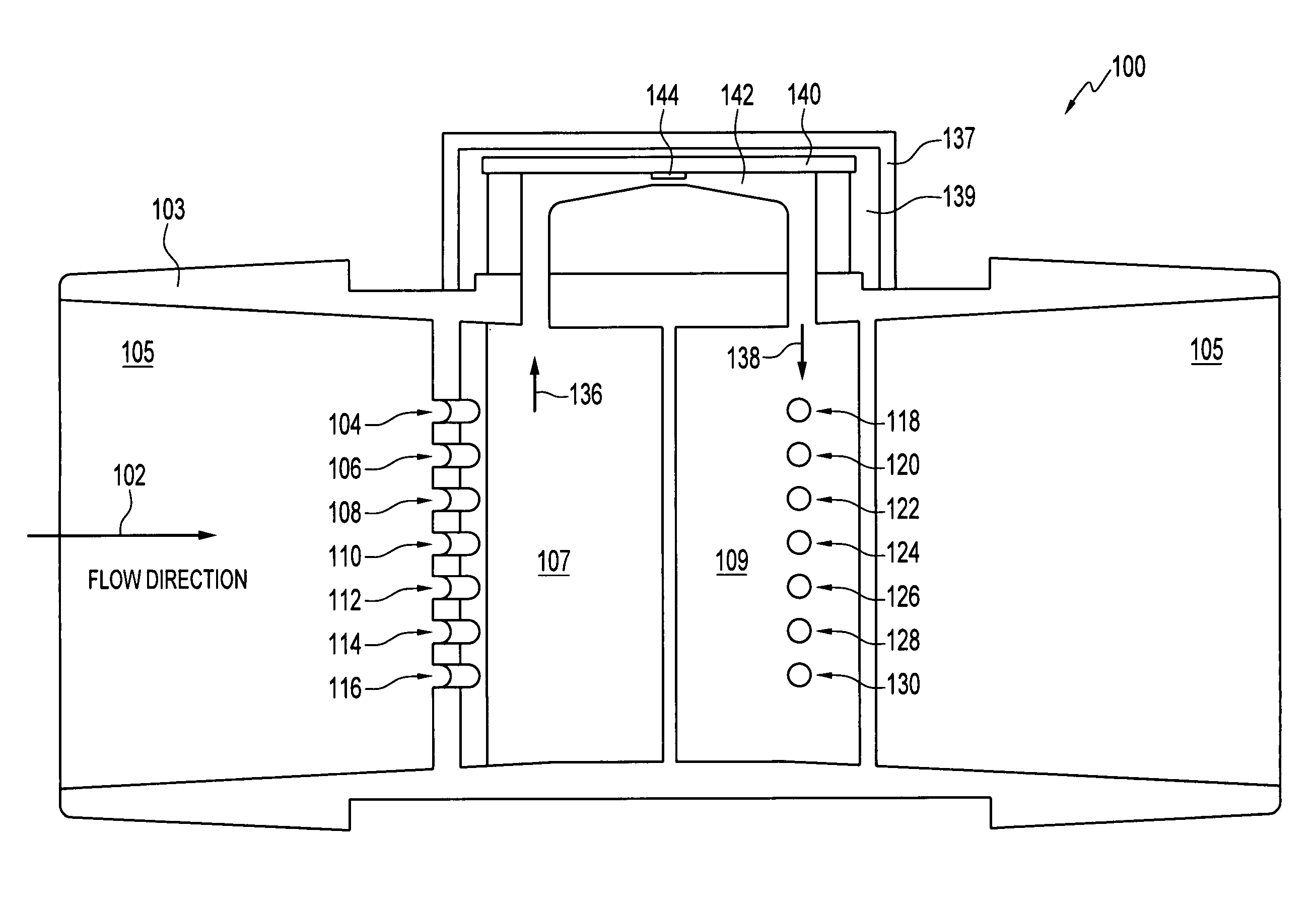
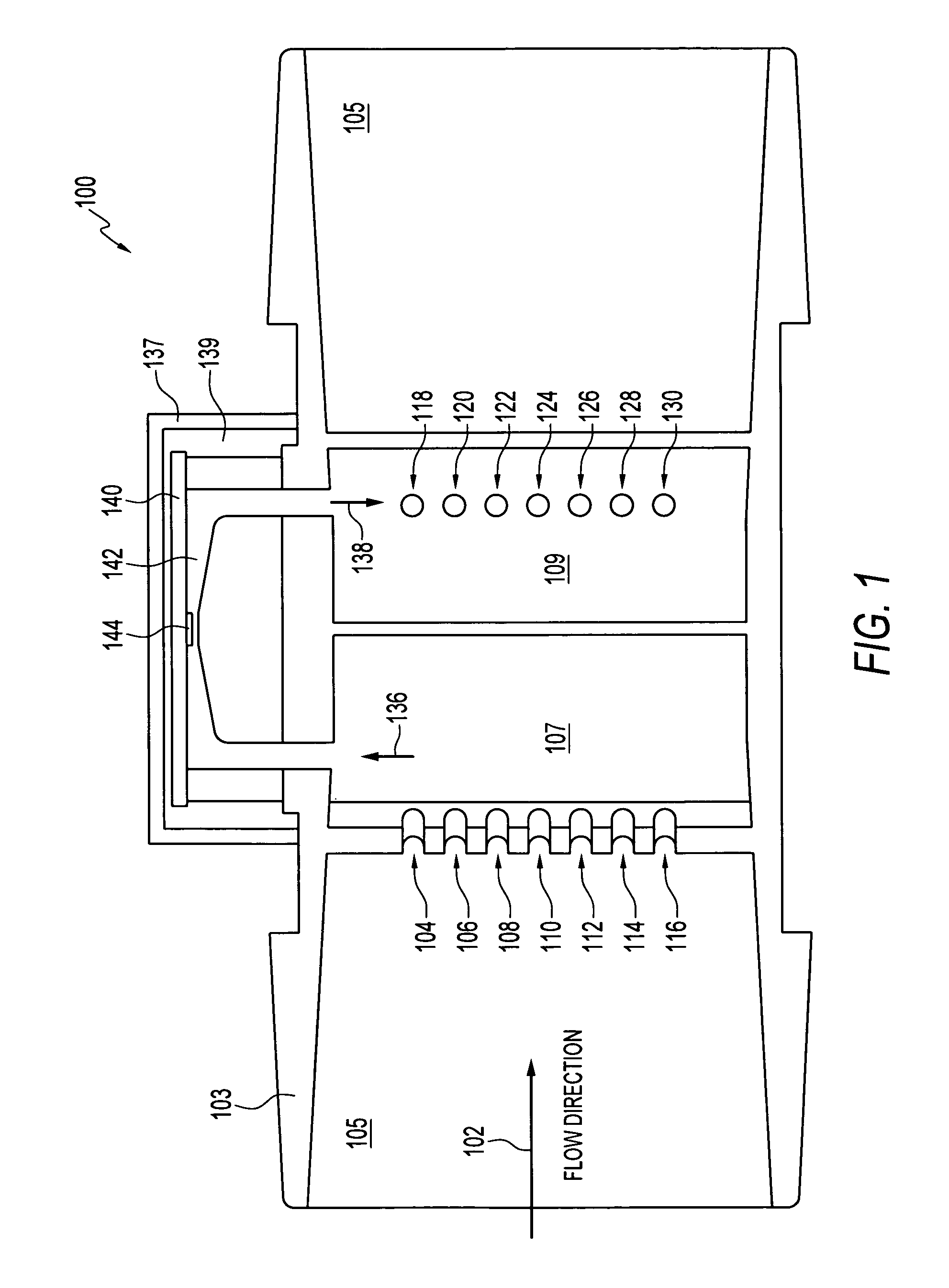
[0025]FIG. 1 illustrates a fluid velocity sensor apparatus 100 a flow channel 105 through which a fluid can flow as indicated by arrow 102. Note that as utilized herein the term “fluid” can refer to a liquid or a gas. The flow channel 105 can be defined by a flow channel wall 103. One or more upstream taps 104, 106, 108, 110, 112, 114, and 116 can be oriented upstream in flow channel 105 to face into the direction of fluid (e.g., gas) flow. The taps 104, 106, 108, 110, 112, 114, and 116 can be implemented as inlet taps that face into the flow of fluid indicated by arrow 102. As utilized herein, the term “tap” can refer to a small opening that permits flow of a liquid or gas.

[0026]Apparatus 100 additionally includes one or more downstream taps 118, 120, 122, 124, 126, 128, and 1...


PUM


Abstract

A fluid velocity sensor includes a sensor die for detecting a fluid property of a fluid flowing through a low resistance flow channel defined by a flow channel wall. One or more tap can be oriented facing into a direction of a flow stream of a fluid flowing through a flow channel defined by a channel wall, wherein the tap(s) leads to the low resistance flow channel, which directs the flow to the sensor die. At least one or more other taps can be located to face perpendicular to the direction of flow, such that the fluid after passing over the sensor die continues on a low resistance path to the other tap(s) facing perpendicular to the direction of flow in order to determine a velocity pressure based on a difference between pressures. The fluid velocity sensor can be arranged in a uni-directional or bi-directional fluid flow configuration.

Description

TECHNICAL FIELD[0001]Embodiments are generally related to sensing devices and methods. Embodiments are also related to the field of fluid velocity measurement.BACKGROUND OF THE INVENTION[0002]Many processes and devices make use of moving fluids. Some examples are heating and ventilating systems that make use of moving air, as well as manufacturing processes that rely on the use and flow of various gasses. Typically, for these processes and / or devices, it is important that the flowrate of the fluid be accurately determined. Accordingly, various techniques to determine the flowrate of a fluid have been developed.[0003]One area where flow sensors find particular usefulness is in medical ventilators. Medical ventilator systems have been long used to provide supplemental oxygen support to patients unable to breathe normally on their own accord. Such devices typically comprise a source of pressurized air or oxygen-rich air which is fluidly connected to the patient through a fluid conduit....

Claims


Application Information

Patent Timeline
Patent Type & Authority Patents(United States)
IPC IPC(8): G01F1/46
CPCG01F1/46G01F1/6845G01F1/72G01F5/00G01F1/684
Inventor SPELDRICH, JAMIE W.
Owner HONEYWELL INT INC
Why Eureka
Try Eureka