Tape fed miniature air gap inspection crawler

a technology of air gap inspection and tape feed, which is applied in the field of miniature robotic devices, can solve the problems of omission of generator field and stator core inspection, general failure to achieve inspection task in a satisfactory manner, and limited use of procedures

Active Publication Date: 2008-03-18
GENERAL ELECTRIC CO
View PDF6 Cites 6 Cited by
  • Summary
  • Abstract
  • Description
  • Claims
  • Application Information

AI Technical Summary

Problems solved by technology

The costs of the disassembly and removal of the generator field, the time it takes to complete this process, and the dangers inherent in generator field removal have led to the occasional omission of the examination of the generator field and the stator core from routine outage schedules.
These procedures generally have not accomplished the inspection task in a satisfactory manner.
Although these known devices are adequate for in-situ generator inspections, they are largely limited to use with entrance gaps that are greater than about one half inch (about 12.7 millimeters).

Method used


Image

  • Tape fed miniature air gap inspection crawler
  • Tape fed miniature air gap inspection crawler
  • Tape fed miniature air gap inspection crawler

Examples


Embodiment Construction

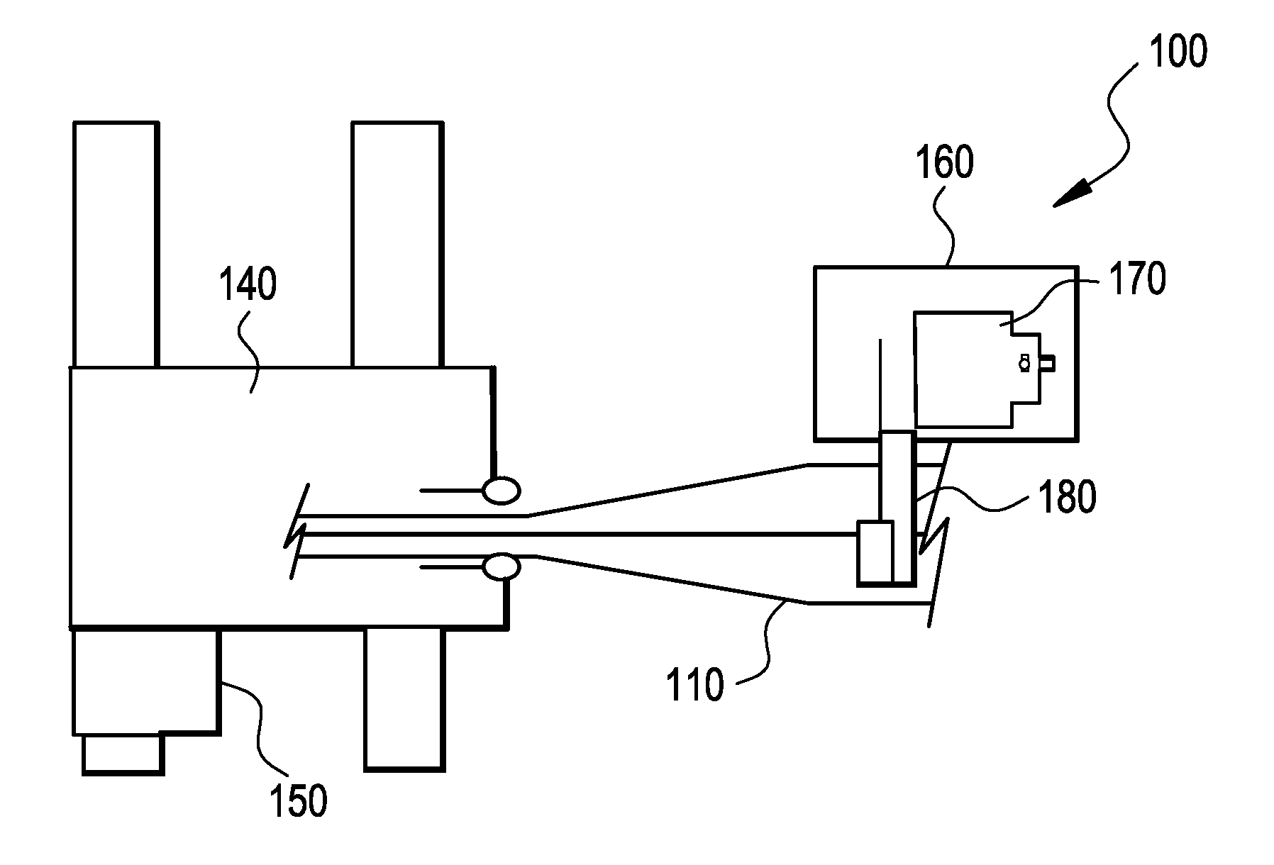
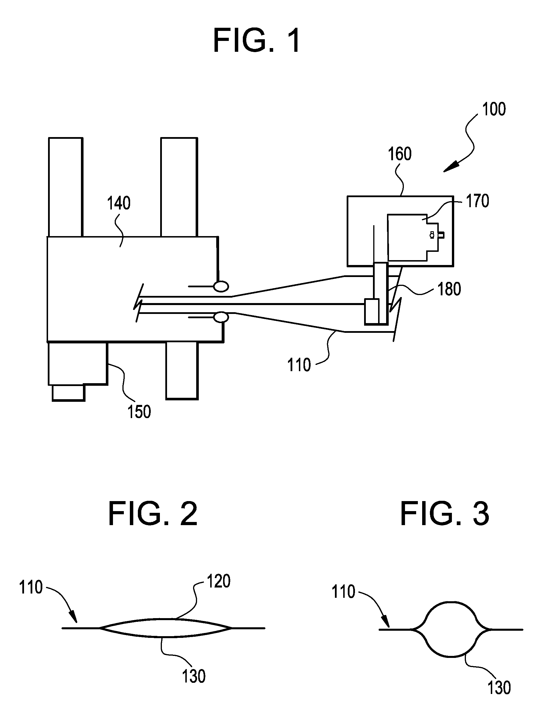
[0020]Referring now to the drawings, in which like numerals refer to like elements throughout the several view, FIGS. 1-3 show a miniature air gap inspection crawler 100 as is described herein. The miniature air gap inspection crawler 100 includes an extendable mast 110.

[0021]The mast 110 may be largely in the form of a collapsible tube with a first side 120 and a second side 130. The mast 110 preferably is made from a somewhat rigid material but with some flexibility and memory. Examples of such materials include spring steel, nickel alloy, carbon fiber composites, and similar types of materials. As is shown in FIGS. 2 and 3, the mast 110 may have a collapsed profile in which the sides 120, 130 are close together and largely flat and an expanded profile in which the sides 120, 130 flex and separate from each other. The sides 120, 130 may be welded together lengthwise or the sides 120, 130 may be joined by adhesives, mechanical fasteners or similar techniques. Other types of expanda...


PUM


Abstract

An air gap inspection device. The air gap inspection device may include a mast and an inspection head attached to the mast. The mast may be in the form of a collapsible tube.

Description

TECHNICAL FIELD[0001]The present application relates generally to a miniature robotic device and more particularly relates to a miniature robotic device for performing in-situ inspections of a generator field and stator core.BACKGROUND OF THE INVENTION[0002]The visual inspection of a generator field and a stator core should be performed on a periodic basis. Conventional generator field / stator core inspection and testing procedures typically require the complete disassembly of the stator core and the removal of the generator field before any inspections or tests can be performed on the unit. The costs of the disassembly and removal of the generator field, the time it takes to complete this process, and the dangers inherent in generator field removal have led to the occasional omission of the examination of the generator field and the stator core from routine outage schedules.[0003]In-situ inspections of generators have been performed by employing poles, trolleys, and field turning te...

Claims


Application Information

Patent Timeline
Patent Type & Authority Patents(United States)
IPC IPC(8): G01M19/00G01M99/00
CPCG01R31/34H02K15/00
Inventor BAGLEY, PAUL C.HATLEY, KENNETHRONEY, ROBERT M.
Owner GENERAL ELECTRIC CO
Why Eureka
Try Eureka