
Fluid container

a technology of fluid containers and containers, which is applied in the direction of rigid containers, liquid transfer devices, transportation and packaging, etc., can solve the problems of complicated fluid pouring, unpredictable flow path of fluid, and obstruction of the fill port of the fluid reservoir, etc., and achieve the effect of convenient vertical stacking

Inactive Publication Date: 2006-05-23
B & B
View PDF15 Cites 6 Cited by
  • Summary
  • Abstract
  • Description
  • Claims
  • Application Information

AI Technical Summary

Benefits of technology

"The present invention is a new and improved fluid container with a collapsible tube that can be extended and retracted for adding fluids to containers or engines. The container has a housing with an opening and a channel for receiving the collapsible tube when in a retracted position. The collapsible tube is permanently attached to the housing and can be manually extended and retracted. The channel allows multiple containers to be stacked vertically, making them easy to store and display. The technical effects of this invention include improved storage and display capabilities, as well as convenient and easy access to fluids for adding to containers or engines."

Problems solved by technology

A problem arises when the fill port of the fluid reservoir is obstructed, i.e., for example, when the fill port is surrounded by other engine components and accessories, tubing, electrical wiring and the like.
Thus, the obstruction results in the terminal end or lip of the container spout not being directly at the fill port but being elevated above the fill port.
Consequently, pouring of the fluid without spillage is complicated by (a) the distance from, i.e., above, the fill port, and (b) the mechanics of the liquid being poured, particularly high viscosity fluids.
As a result, the flow path of the fluid becomes unpredictable and spillage is more likely to occur.
Another problem exists with conventional fluid containers such as those employing the container design characterized by the narrow neck and spout extending above the main body thereof.
Because of their design, these conventional fluid containers cannot be conveniently or easily stacked on store shelves or in shipping cartons.
Consequently, available shelf space is wasted since a second fluid container of this design cannot conveniently be stacked above a first fluid container of the same type.

Method used


Image

  • Fluid container
  • Fluid container
  • Fluid container

Examples


Embodiment Construction

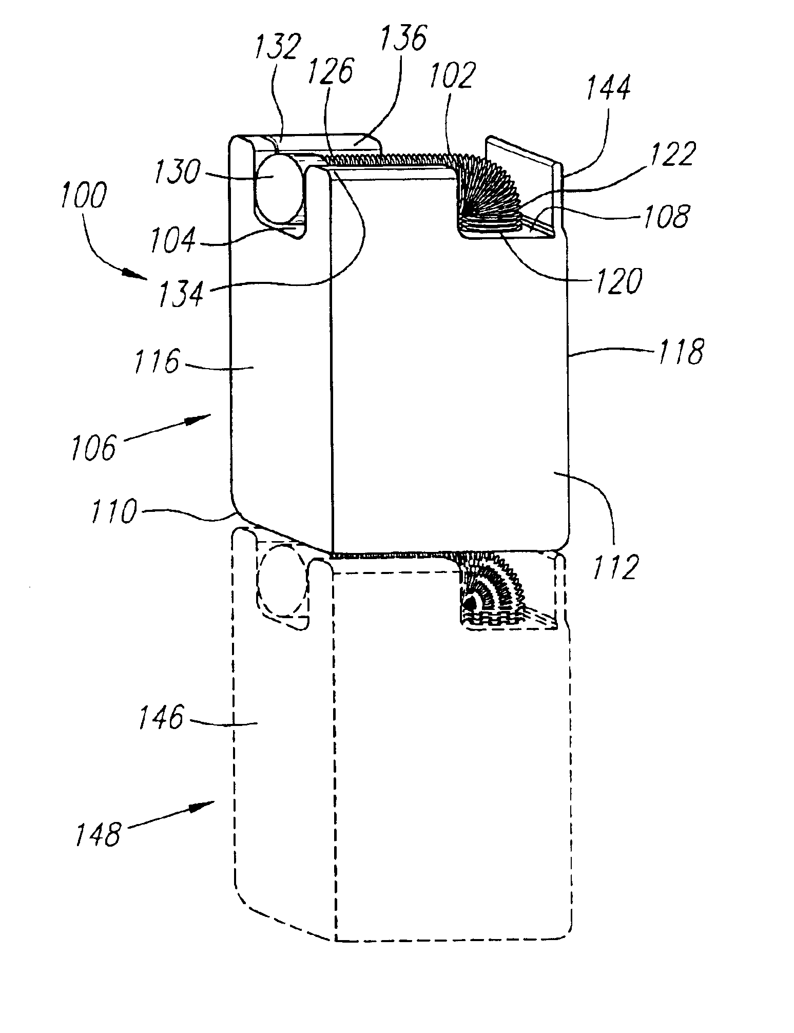
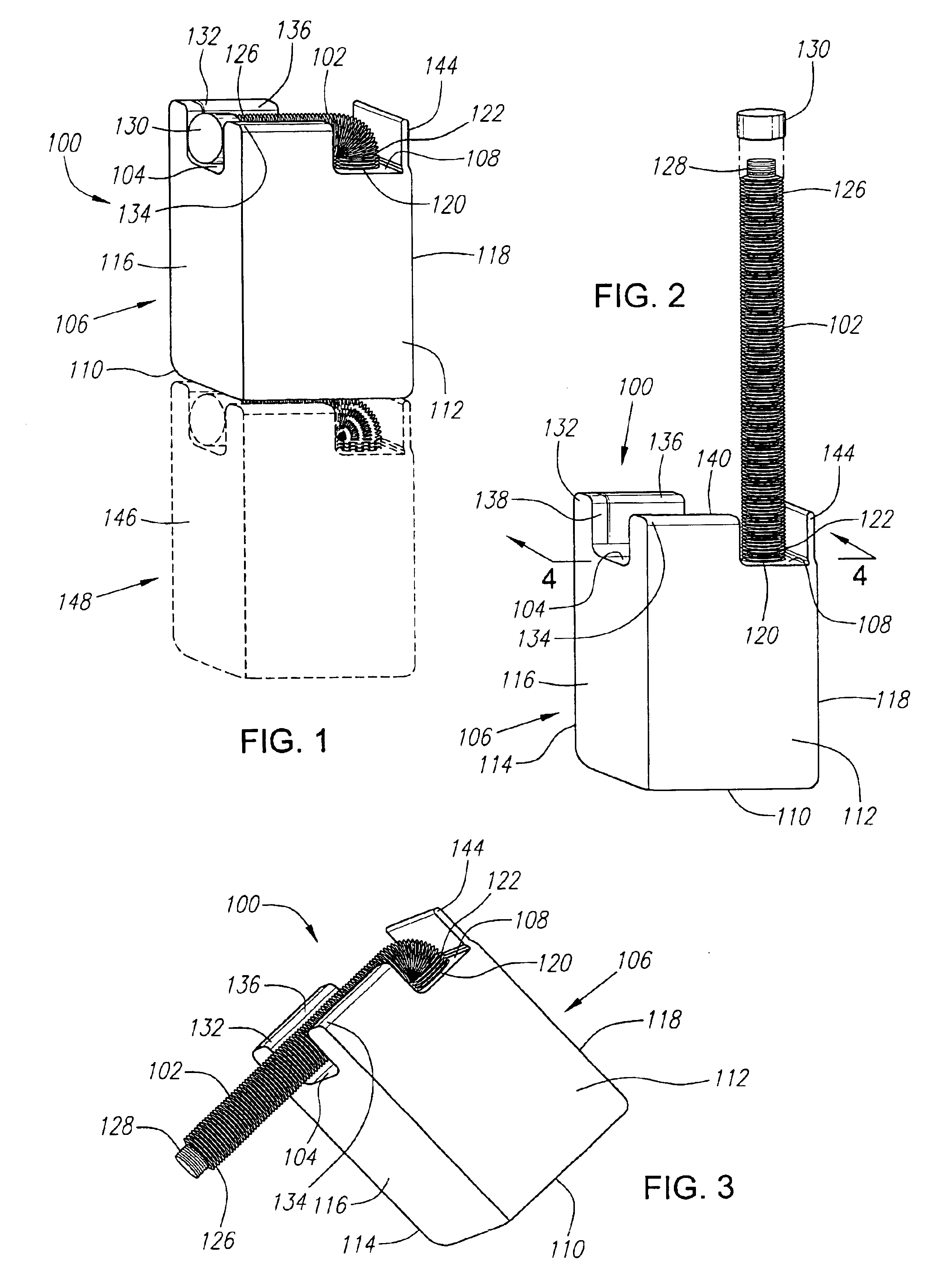
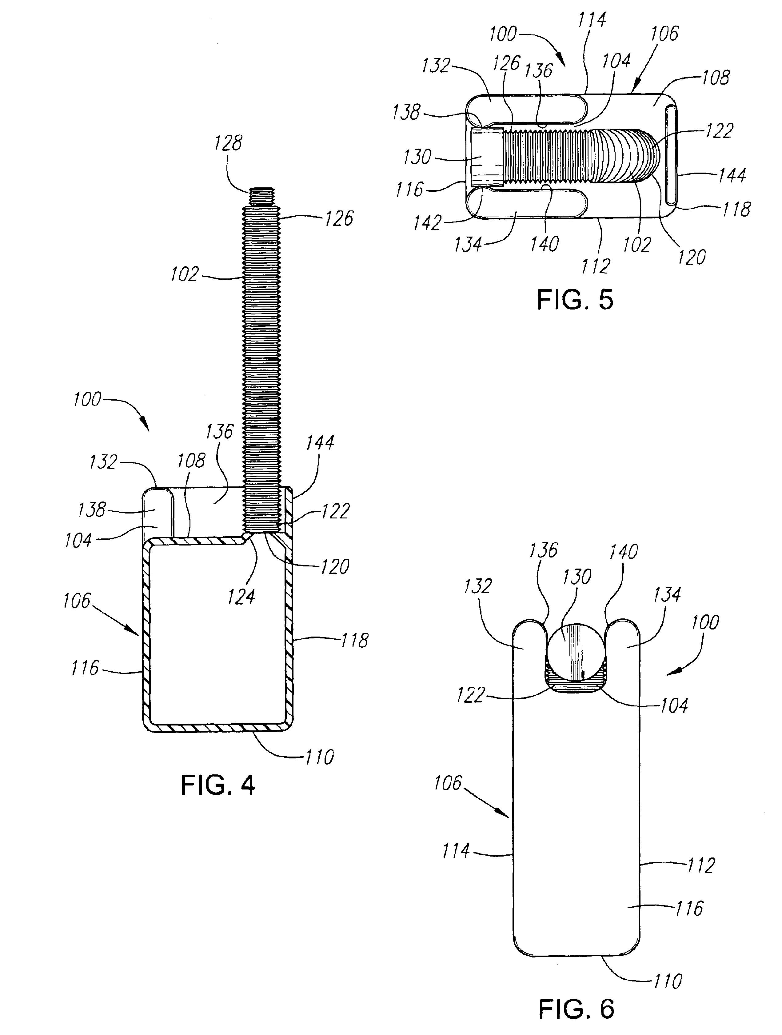
[0024]The present invention is a fluid container 100 having a permanently attached collapsible tube 102 exhibiting a bellows-like or accordion-like construction in combination with an external molded channel 104 for nesting the collapsible tube 102 in a retracted lateral position. This construction facilitates vertical stacking of a plurality of the fluid containers 100 for storage, shipping and display purposes. The fluid container 100 of the preferred embodiment is shown in FIGS. 1-6 and is typically employed by persons for use in inserting a variety of initial or replacement fluids into a fill port (not shown) of, for example, an engine or other container where the fill port is obstructed or otherwise not conveniently accessible.

[0025]In the preferred embodiment, the fluid container 100 can be comprised of, for example, a rectangular housing 106 best shown in FIGS. 1-3 and preferably comprised of flexible but sturdy plastic. The rectangular housing 106 includes a top surface 108,...


PUM


Abstract

A fluid container for use in accessing an obstructed fill port of a machine for inserting fluids therein includes a housing for containing a fluid, the housing having a top surface with an opening formed therein. A collapsible tube is aligned with the opening and affixed to the housing for providing a fluid exit path, the tube being manually extended and retracted. A channel is formed on the top surface of the housing for receiving the collapsible tube when the tube is in a retracted lateral position. An alternative embodiment of the fluid container exhibits a molded pocket formed beneath the bottom surface of a first housing for receiving a collapsible tube of a second housing when the collapsible tube of the second housing is in a retracted lateral position. Both the channel and the molded pocket facilitate vertical stacking of the containers.

Description

BACKGROUND OF THE INVENTION[0001]1. Technical Field[0002]The present invention relates to fluid containers. More specifically, the present invention relates to methods and apparatus for a fluid container having a permanently attached collapsible tube exhibiting a bellows-like construction in combination with an external molded channel for nesting the collapsible tube in a retracted lateral position, the container for use in inserting fluids into a fill port that is obstructed or otherwise not conveniently accessible.[0003]2. Background Art[0004]Fluid containers have long been known and used for containing fluids for many different uses and applications. One common application for these containers is for containing replacement fluids for engines such as, for example, oil, transmission fluid, brake fluid and the like. Many of these fluid containers are designed and configured for pouring the replacement fluid into the appropriate fluid reservoir with a minimum of spillage of the fluid...

Claims


Application Information

Patent Timeline
Patent Type & Authority Patents(United States)
IPC IPC(8): B67D5/60B67D7/78B65D21/02B65D25/46
CPCB65D25/465B65D21/0231
Inventor BARNETT, BURTONBRODY, KENNETH I.
Owner B & B
Learn More