Laser Scanner System And Registration Method Of Point Cloud Data

a laser scanner and point cloud technology, applied in the field of laser scanners, can solve the problems of complicated work, inability to acquire point cloud data of a shaded portion, etc., and achieve the effect of simplifying system configuration, simplifying processing, and improving registration speed

Active Publication Date: 2018-03-29
KK TOPCON
View PDF18 Cites 16 Cited by
  • Summary
  • Abstract
  • Description
  • Claims
  • Application Information

AI Technical Summary

Benefits of technology

[0009]It is an object of the present invention is to provide a laser scanner system and a registration method of point cloud data which facilitate an installation operation of a laser scanner or facilitate a combination of a plurality of point cloud data in a case where the point cloud data are acquired from a plurality of points.
[0015]According to the present invention, the laser scanner system comprises a laser scanner which includes a distance measuring light emitting unit for emitting a distance measuring light, a distance measuring unit for receiving a reflection light from an object to be measured and performing a distance measurement, a scanning unit for rotatably irradiating the distance measuring light, a frame unit on which the scanning unit is provided and capable of rotating horizontally, a leveling unit for leveling the frame unit, a directional angle detecting unit for detecting an irradiating direction of the distance measuring light, a GNSS device, and a control arithmetic unit, wherein the laser scanner is installed at two points, and the frame unit is leveled by the leveling unit, and wherein the control arithmetic unit obtains global coordinates of installation positions of the laser scanner from the GNSS device respectively, scans the distance measuring light over a total circumference at each of the installation positions, acquires point cloud data of the total circumference, relatively rotates two point cloud data around a vertical axis as a center, performs a shape matching of the two point cloud data and combines the two point cloud data. As a result, there is no need that a directional angle of the laser scanner at the installation point is known, and a system configuration can be simplified. Further, since the shape matching of the plurality of the point cloud data is performed only by a rotation in one direction, processings can be simplified, and a speed of a registration processing can be higher.
[0016]Further, according to the present invention, the registration method of the point cloud data comprises a step of installing a laser scanner including a GNSS device at two arbitrary points, a step of vertically leveling the laser scanner, a step of obtaining a global coordinate value of the laser scanner at the two points by the GNSS device, a step of acquiring point cloud data from the two points, respectively, a step of converting the point cloud data into a global coordinate system based on the global coordinate value, a step of relatively rotating the two point cloud data around a vertical axis as a center, performing a shape matching of the two point cloud data and combining the two point cloud data. As a result, there is no need that the directional angle of the laser scanner at the installation position is known, and the system configuration can be simplified. Further, since the shape matching of the plurality of the point cloud data is performed only by the rotation in one direction, the processings can be simplified, and the speed of the registration processing can be higher.

Problems solved by technology

Further, in a case where the object to be measured is a structure such as a building or the like, if a measurement is performed from one direction, point cloud data of a shaded portion cannot be acquired.
For this reason, there is a problem that a work is complicated.

Method used


Image

  • Laser Scanner System And Registration Method Of Point Cloud Data
  • Laser Scanner System And Registration Method Of Point Cloud Data
  • Laser Scanner System And Registration Method Of Point Cloud Data

Examples


first embodiment

[0067]Next, by referring to FIG. 3 and FIG. 4, a description will be given on a laser scanner system and a registration method according to the present invention.

[0068]The laser scanner system has at least one laser scanner 1. Further, the laser scanner 1 is installed at an arbitrary position which is suitable for scanning an object to be measured (not shown). In FIG. 3, although two laser scanners 1 are shown, the laser scanner 1 is actually installed at a point A, and then installed at a point B after the measurement as required is completed.

[0069]It is to be noted that the laser scanner 1 does not have a mechanism for measuring an azimuth angle such as a compass, or the like. Therefore, when the laser scanner 1 is installed at the point A or the point B, a direction of the laser scanner 1 is unknown, and a direction of the point B with respect to the point A and the direction of the point A with respect to the point B are unknown.

[0070](Step 01) First, the laser scanner 1 is inst...

second embodiment

[0100]Therefore, in the second embodiment, Step 19 and Step 20 are general matching processings for narrowing down a range where the shape matching of the point cloud data A and the point cloud data B with high density is performed. The control arithmetic unit 15 sets a detailed matching range including an error in the general matching processings mainly around a shape matching result of the general matching processings.

[0101](Step 21) When the general matching processing is finished, the control arithmetic unit 15 finally performs a registration program and performs a combination (a registration) processing between the point cloud data A and the point cloud data B which are precise point cloud data.

[0102]In a state where the point cloud data B is rotated around the vertical axis as the center by a predetermined angle, e.g., the same rotation angle as the general matching processing at Step 19, the point cloud data A is rotated one round (360°) around the vertical axis as the center...

third embodiment

[0122]In the third embodiment, after image matching is performed between the total circumferential image A acquired at the point A and the total circumferential image B acquired at the point B, the detailed shape matching is performed between the point cloud data A and the point cloud data B, and the registration is performed.

[0123]Therefore, a range for performing the detailed shape matching can be narrowed down by the image matching, and it would suffice if the detailed shape matching is performed only within a detailed matching range. As a result, a speed of a registration processing can be higher.

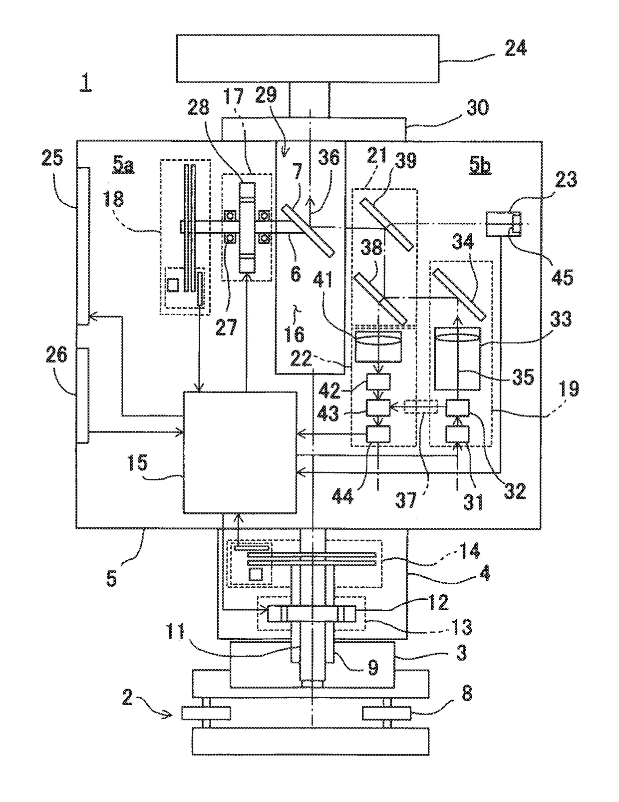
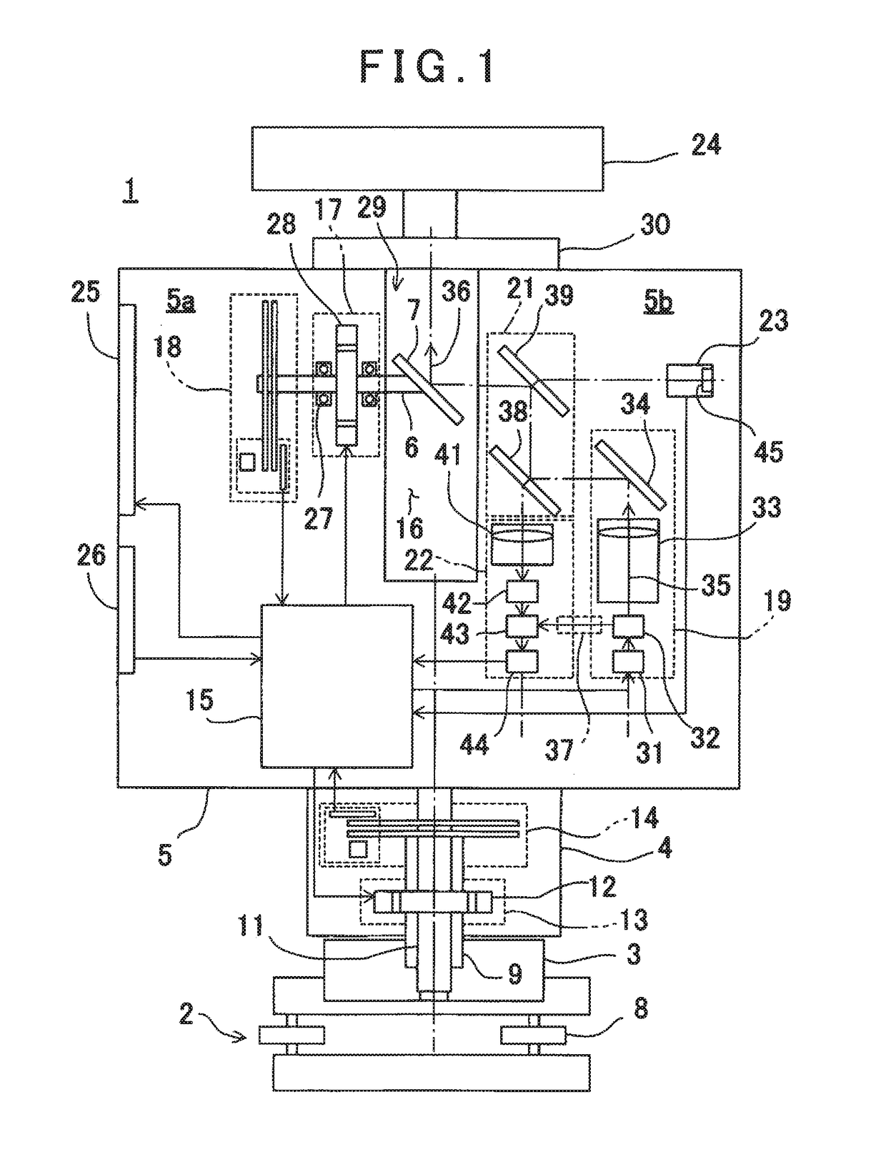
[0124]Next, by referring to a flowchart in FIG. 7, a description will be given on a registration method according to a fourth embodiment of the present invention. It is to be noted that, in the fourth embodiment, since a configuration of a laser scanner 1 (see FIG. 1) and a laser scanner system is the same as the first embodiment, a detailed description thereof will be omitted.

[0125](St...


PUM


Abstract

The invention provides a laser scanner system, which comprises a laser scanner which includes a distance measuring unit for receiving a reflection light of a distance measuring light from an object to be measured and performing a distance measurement, a scanning unit for rotatably irradiating the distance measuring light, a directional angle detecting unit for detecting an irradiating direction of the distance measuring light, a GNSS device, and a control arithmetic unit, wherein the laser scanner is installed at two points, and wherein the control arithmetic unit obtains global coordinates of installation positions of the laser scanner from the GNSS device respectively, scans the distance measuring light over a total circumference at each of the installation positions, acquires point cloud data of the total circumference, performs a shape matching of the two point cloud data and combines the two point cloud data.

Description

BACKGROUND OF THE INVENTION[0001]The present invention relates to a laser scanner system which acquires point cloud data from a plurality of points by a laser scanner and integrates a plurality of point cloud data as point cloud data of the same coordinate system and a registration method of the point cloud data.[0002]As a measuring instrument for acquiring three-dimensional data of an object to be measured, a laser scanner is used. The laser scanner scans a distance measuring light and acquires point cloud data of an object to be measured or a range to be measured. Based on the point cloud data as acquired, a shape and the three-dimensional data of the object to be measured can be determined.[0003]Further, in a case where the object to be measured is a structure such as a building or the like, if a measurement is performed from one direction, point cloud data of a shaded portion cannot be acquired. For this reason, the point cloud data of the object to be measured are acquired from...

Claims


Application Information

Patent Timeline
Patent Type & Authority Applications(United States)
IPC IPC(8): G01C11/02G01S17/02G01S17/89G01C15/00G01S17/86
CPCG01C11/025G01S17/023G01S17/89G01C15/006G01S7/4808G01S17/86G01C15/002
Inventor KOMEICHI, TAKAHIROITO, TADAYUKIYOSHINO, KEN-ICHIRO
Owner KK TOPCON
Why Eureka
Try Eureka