Rotary compressor having a discharge valve

a technology of rotary compressor and discharge valve, which is applied in the direction of positive displacement liquid engine, piston pump, liquid fuel engine, etc., can solve the problems of undesirable noise and/or premature wear of the valve head, and limit the tangential movement of the valve head. , to prevent the effect of tangential movement of the valve head

Inactive Publication Date: 2008-03-18
TECUMSEH PROD CO
View PDF42 Cites 60 Cited by
  • Summary
  • Abstract
  • Description
  • Claims
  • Application Information

AI Technical Summary

Benefits of technology

[0010]The present invention includes a valve assembly mounted to a rotor such that the movement of the valve head towards and away from the discharge port in the rotor is substantially linear during the operation of the compressor. To compensate for the tangential forces described above, in one embodiment, the path of the valve head displacement is canted or aligned obliquely with respect to the axis of rotation of the rotor. In this embodiment, the path of the valve head is aligned such that it is substantially co-linear with the resultant force vector applied to the valve head, where the resultant force vector comprises the combined force of the tangential and radial forces applied to the valve head. As a result, in operation, the valve head will lift away from and return to the valve seat along a substantially linear path of displacement, as opposed to being displaced along a substantially curvilinear or undesirable path, as described above. Accordingly, there is less opportunity for the valve head to be misaligned with respect to the valve seat. As discussed above, an improperly seated valve head may allow working fluid to escape the compression chamber insufficiently pressurized, thus rendering the compressor inoperable or inefficient. Further, a misaligned valve head may also cause the valve head to impact the valve seat with additional force and thus cause undesirable noise and / or premature wear of the valve head.
[0011]In other embodiments, an external guide may be provided to guide the valve head and thus limit the valve head's tangential movement. Further, a guide can be positioned internal to the valve head to likewise prevent tangential movement of the valve head.

Problems solved by technology

As discussed above, an improperly seated valve head may allow working fluid to escape the compression chamber insufficiently pressurized, thus rendering the compressor inoperable or inefficient.
Further, a misaligned valve head may also cause the valve head to impact the valve seat with additional force and thus cause undesirable noise and / or premature wear of the valve head.

Method used


Image

  • Rotary compressor having a discharge valve
  • Rotary compressor having a discharge valve
  • Rotary compressor having a discharge valve

Examples


Embodiment Construction

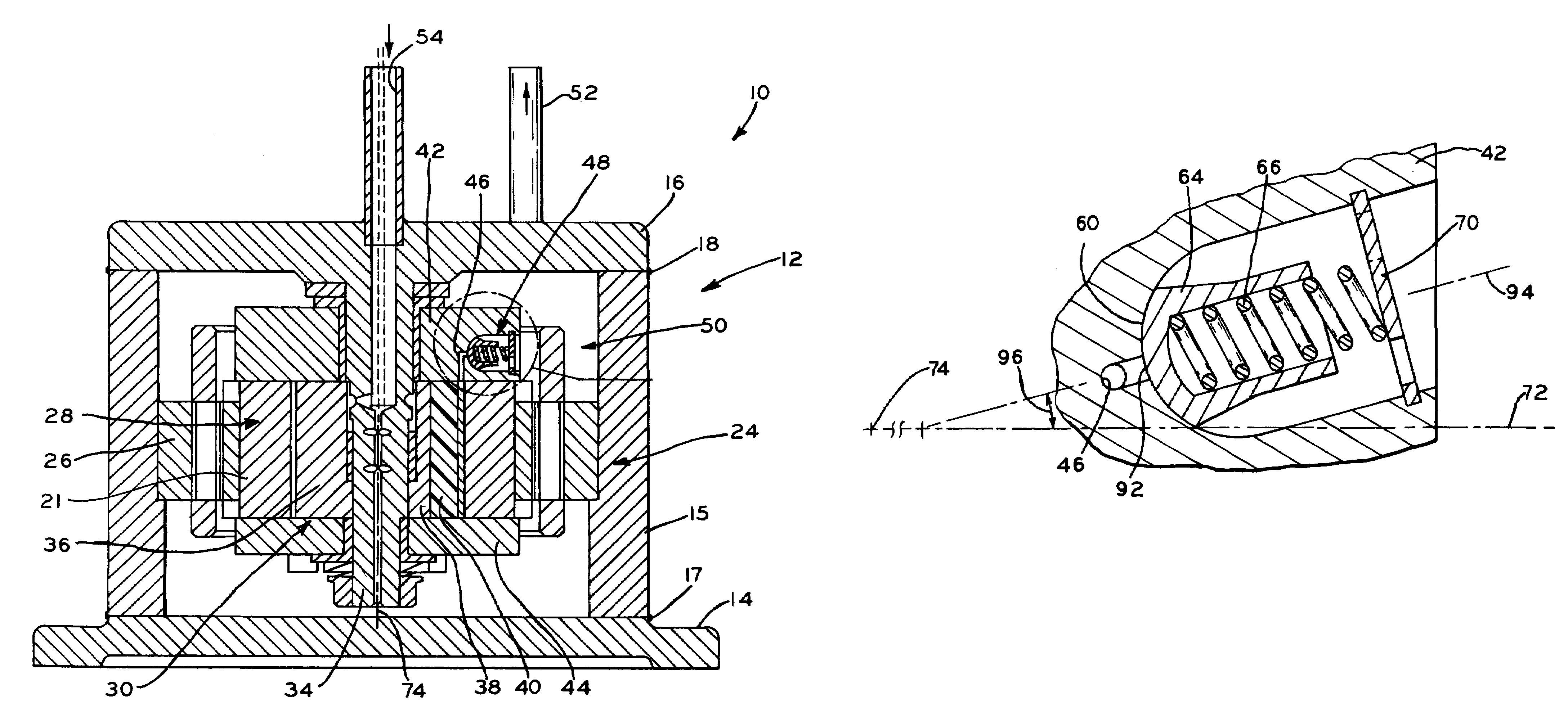
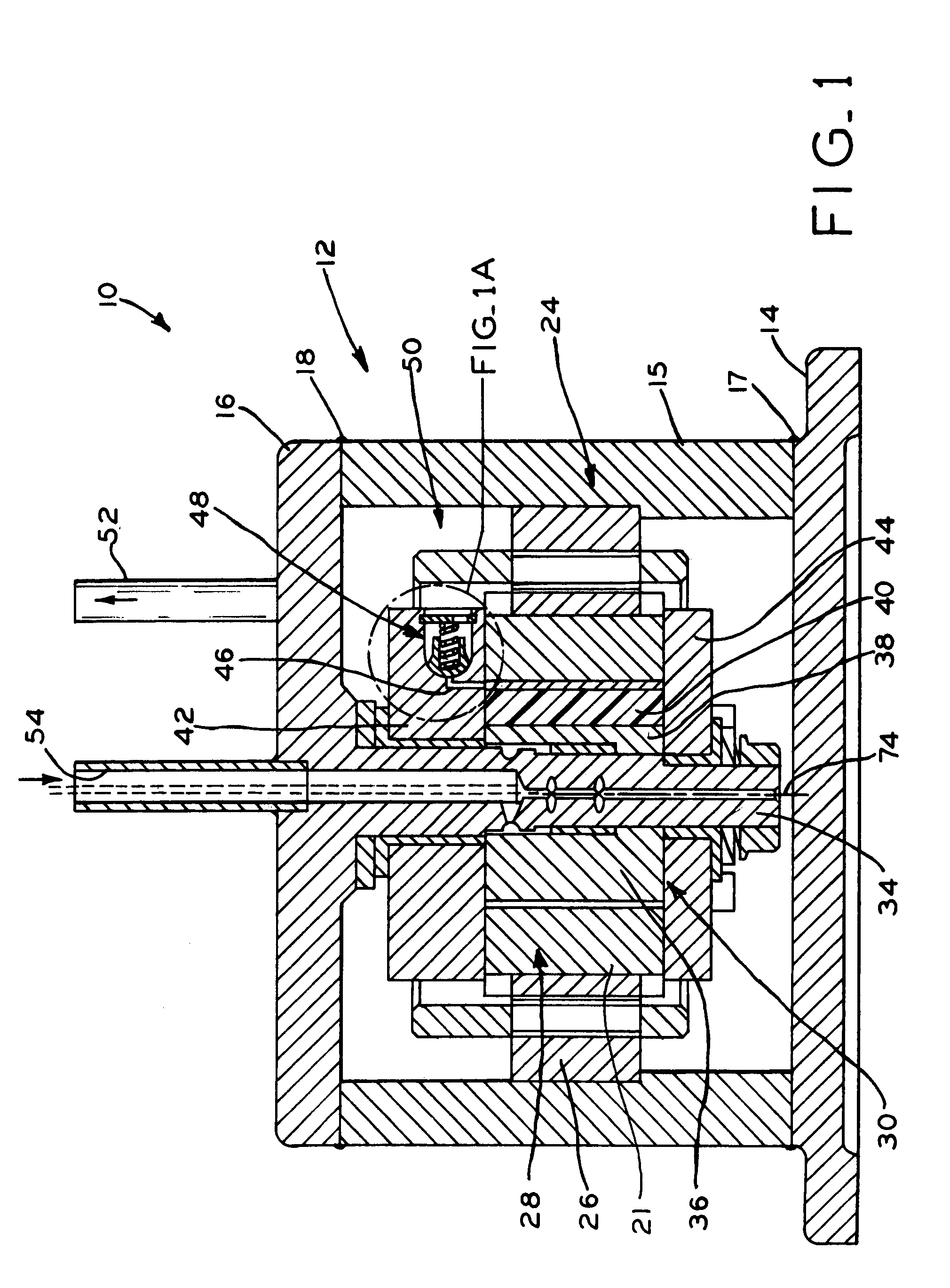
[0031]Referring to FIGS. 1-4, an exemplary rotary compressor 10 includes a hermetically sealed housing 12 including base 14, annular side wall 15 and top wall 16. Base 14 is hermetically sealed to wall 15 by welding, brazing, or the like at location 17. Similarly, side wall 15 is hermetically sealed to top wall 16 by welding, brazing, or the like at location 18. Compressor 10 includes electric motor 24 having stator 26 and rotor 28 which defines a portion of compression mechanism 30. Compression mechanism 30 compresses a refrigerant, such as carbon dioxide, for example, from a low pressure to a higher pressure for use in a refrigeration system, for example. Stator 26 is rigidly mounted within housing 12 and circumscribes rotor 28. Extending through rotor 28 is stationary shaft 34 which is, in this embodiment, integrally formed with top wall 16. During operation, stator 26 generates a rotating electromagnetic field to rotationally drive rotor 28, having permanent magnets 29 mounted i...


PUM


Abstract

A rotary compressor having a housing, a rotor positioned within the housing defining a compression chamber, the rotor rotatable about an axis of rotation, a discharge port in the rotor in fluid communication with the compression chamber, and a valve assembly mounted to the rotor to regulate the pressure of the fluid within the compression chamber. In one embodiment, the valve assembly is canted or obliquely aligned with respect to the axis of rotation of the rotor and a radial axis perpendicular to and intersecting the axis of rotation. Aligning the valve assembly in this way allows the displacement of the valve head of the valve assembly to be substantially collinear with forces acting on the valve head.

Description

CROSS REFERENCE TO RELATED APPLICATION[0001]This application claims the benefit under 35 U.S.C. §119(e) of U.S. Provisional Patent Application Ser. No. 60 / 644,653, entitled ROTATING DISCHARGE VALVE, filed on Jan. 18, 2005, the entire disclosure of which is hereby expressly incorporated by reference herein.BACKGROUND OF THE INVENTION[0002]1. Field of the Invention[0003]The present concept relates to rotary compressors. More particularly, the present concept relates to discharge valves for rotary compressors.[0004]2. Description of the Related Art[0005]A typical rotary compressor includes a housing, a stator positioned within the housing, and a rotor driven, i.e., rotated, by the stator, the rotor being mounted to a first end of a crankshaft. The compressor further includes a compression mechanism operably engaged with the opposite end of the crankshaft. The compression mechanism typically includes an eccentric member engaged with the crankshaft that is rotated within a stationary cyl...

Claims


Application Information

Patent Timeline
Patent Type & Authority Patents(United States)
IPC IPC(8): F03C2/00F04C18/00
CPCF04C18/321F04C29/126Y10T137/7927Y10T137/7929
Inventor MANOLE, DAN M.
Owner TECUMSEH PROD CO
Why Eureka
Try Eureka