Arrayable loudspeaker with constant wide beamwidth

a loudspeaker and beamwidth technology, applied in the direction of transducer details, electrical transducers, electrical apparatus, etc., can solve the problems of inability to achieve constant wide beamwidth of multiple transducers, inconvenient operation of multiple transducers, and inability to achieve constant wide beamwidth over the operating frequency range of loudspeakers, so as to achieve uniform beamwidth, and reduce the effect of nois

Active Publication Date: 2018-07-03
MEYER SOUND LABORATORIES
View PDF14 Cites 0 Cited by
  • Summary
  • Abstract
  • Description
  • Claims
  • Application Information

AI Technical Summary

Benefits of technology

[0010]The arrayable loudspeaker system of the present invention avoids these tradeoffs. The invention provides for an arrayable loudspeaker system with broadband pattern control along with adequate compression driver loading, even at relatively low crossover frequencies. The horn mouth dimensions must be quite large in order to achieve this, yet the resulting low driver shadowing issues are substantially eliminated. The issues inherent in other designs—off-axis lobing, inconsistent beamwidth, and inadequate compression driver loading—are substantially eliminated.
[0012]The invention further benefits the arrayable loudspeaker—specifically the line array element—by minimizing cabinet width without sacrificing LF transducer diameter and hence LF efficiency and maximum output. The market demands smaller, lighter, more powerful sound systems, yet overall cabinet size and LF output are generally linked. LF performance can now be maintained from a significantly narrower cabinet, greatly improving audience sightlines with no reduction in performance.

Problems solved by technology

The problem encountered in conventional loudspeakers designed to produce wide beamwidths is that the beamwidth is not stable or constant over the operating frequency range of the loudspeaker, and particularly at mid to low frequencies at and below crossover.
In compact multi-way loudspeaker systems, it is difficult to achieve constant wide beamwidth from multiple transducers.
Existing attempts involve tradeoffs in cabinet size, distortion, lobing, excessive pattern narrowing, and / or phase issues.
These includeplacing cone drivers and waveguide(s) (horn(s)) next to each other—this can result in off-axis narrowing and lobing at crossover frequencies;mounting multiple transducers / horns coaxially—can result in inconsistent beamwidths; forces compromises in transducer / waveguide designs;making the horn very narrow to push cone drivers closer together—this compromises HF driver loading and / or beamwidth consistency;cutting openings in the horn walls for rear-mounted drivers—this compromises LF output or HF driver loading and / or coverage pattern; andusing a single large horn fed by all drivers—this requires much larger enclosure for comparable LF extension and / or efficiency.

Method used


Image

  • Arrayable loudspeaker with constant wide beamwidth
  • Arrayable loudspeaker with constant wide beamwidth
  • Arrayable loudspeaker with constant wide beamwidth

Examples


Embodiment Construction

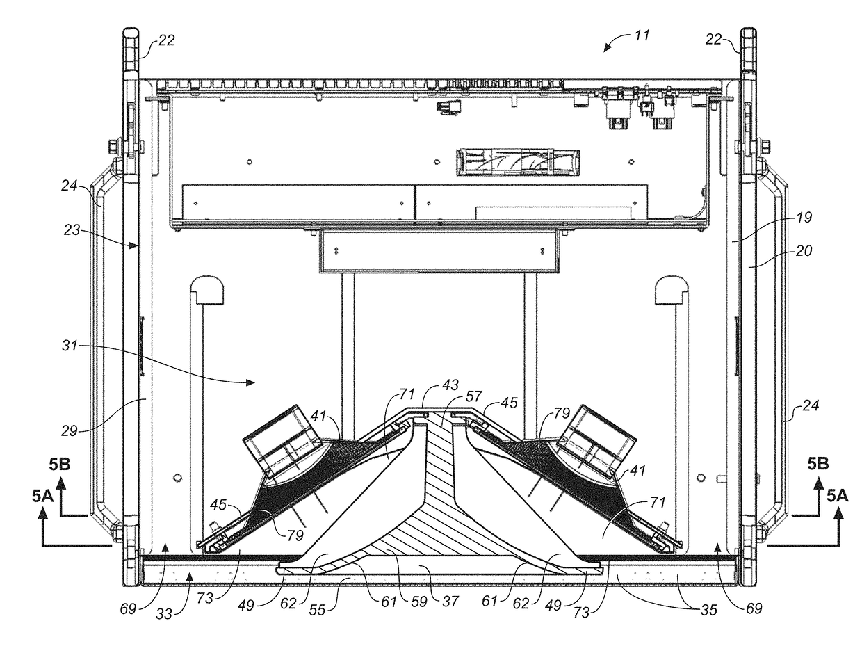
[0038]As used herein “low” and “high” to denote frequency ranges are understood to be relative terms that encompass mid-frequency ranges where crossover from low to high frequencies occurs. For example, when referring to a “low frequency” transducer (sometimes referred to herein as “driver”), it will be understood that the transducer will operate at frequencies below crossover and at frequencies extending up into the crossover frequency range. Similarly, when referring to a “high frequency” transducer, it will be understood that the transducer will operate at frequencies that extend down into the crossover frequency range as well as frequencies above crossover. Also, the characterization of a transducer as “high” or “low” does not preclude the possibility that the transducer could produce some acoustic energy outside of its normal operating frequency range, as is discussed below in connection with the low frequency transducers of the loudspeaker described herein.

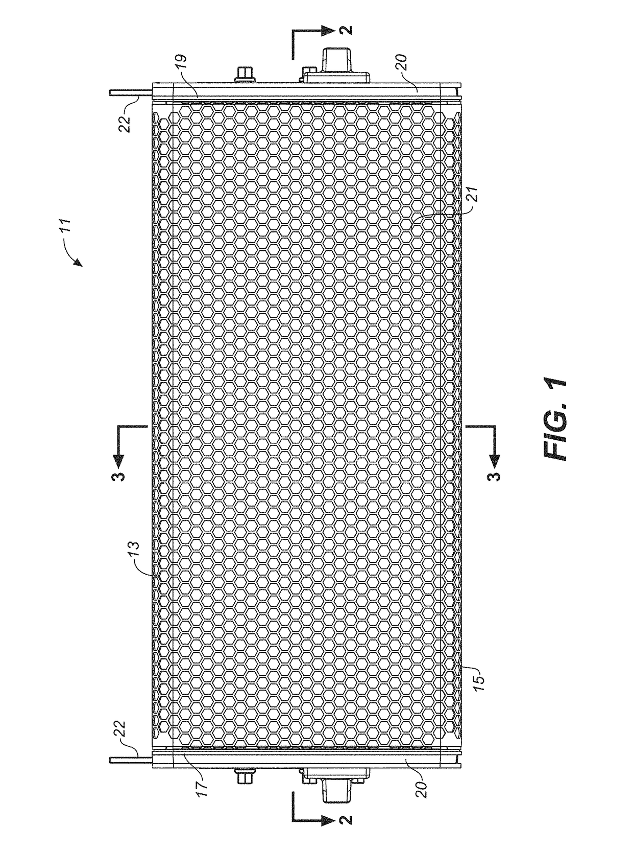
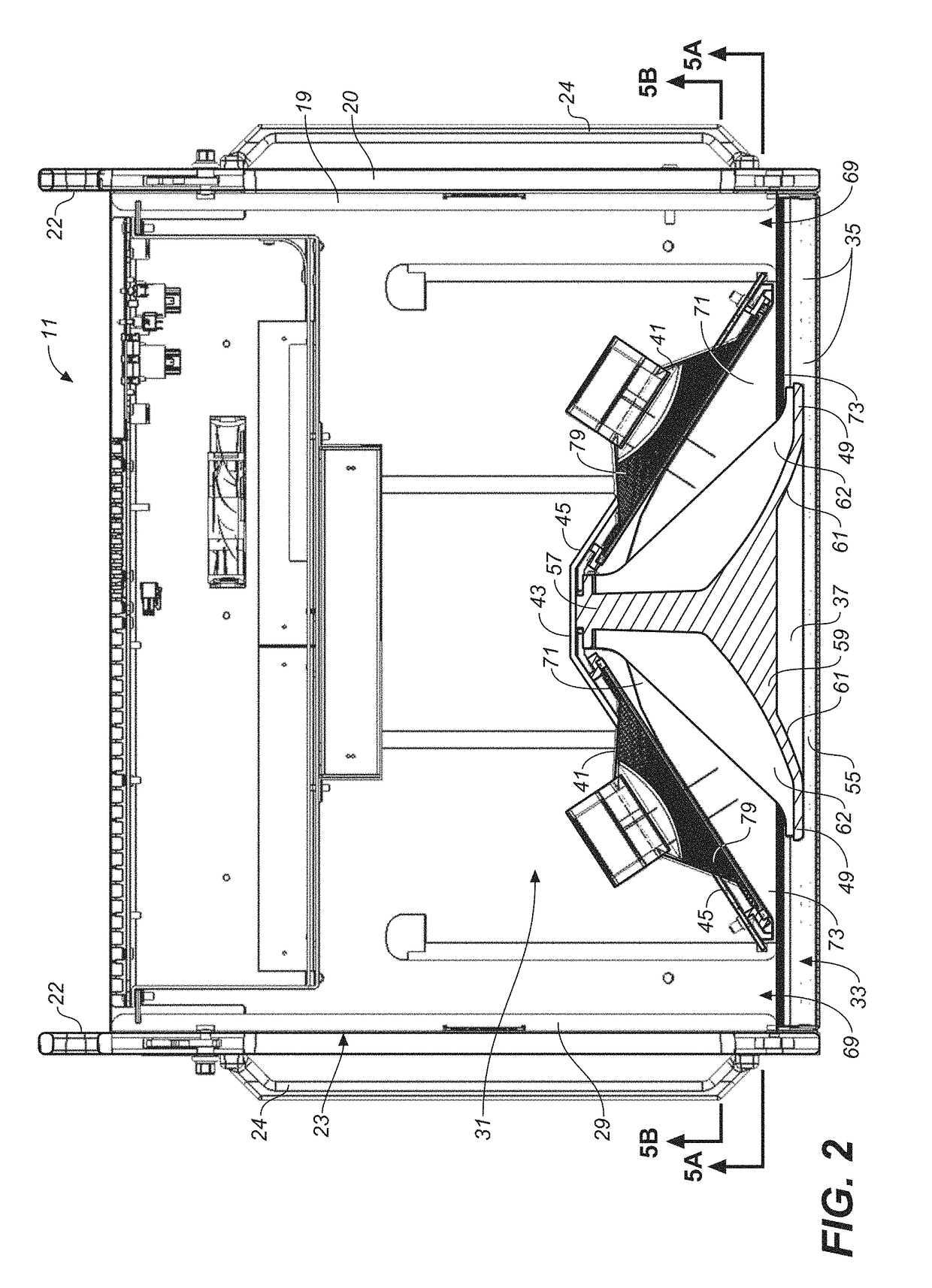
[0039]An arrayable l...


PUM


Abstract

An arrayable loudspeaker (11) has at least one high frequency driver (39) mounted to a horn (37) and at least one pair of low frequency drivers (41) configured behind and in a closely spaced relationship to the horn to form low frequency side chambers (71) between the drivers and the horn from which acoustic energy produced by the low frequency drivers can propagate. Low frequency exit channels (77) above and below the horn are coupled to the low frequency side chambers (71). The configuration of the horn and low frequency drivers and the low frequency side chambers and low frequency exit channels is such that acoustical outputs of all drivers radiate coaxially from the loudspeaker with substantially constant wide beamwidth in the non-arraying plane. Signal processing can be added to enhance beamwidth control critical frequency ranges above crossover.

Description

CROSS-REFERENCE TO RELATED APPLICATIONS[0001]This application claims the benefit of U.S. Provisional Patent Application No. 62 / 147,553 filed Apr. 14, 2015, which is incorporated herein by reference.BACKGROUND[0002]The present invention generally relates to arrayable loudspeaker systems and more particularly to the control of the beamwidth of an arrayed loudspeaker system in the non-arraying plane.[0003]The beamwidth of a loudspeaker determines its coverage. The problem encountered in conventional loudspeakers designed to produce wide beamwidths is that the beamwidth is not stable or constant over the operating frequency range of the loudspeaker, and particularly at mid to low frequencies at and below crossover. A loudspeaker that has a constant beamwidth over its operating frequencies will cover the audience predictably and evenly, with well-defined roll-off points and minimal energy projected beyond the roll-off points. The sound will be the same throughout the loudspeaker's covera...

Claims


Application Information

Patent Timeline
Patent Type & Authority Patents(United States)
IPC IPC(8): H04R9/08H04R3/14H04R1/28H04R1/24H04R1/40
CPCH04R1/24H04R1/2865H04R3/14H04R1/403H04R2203/12H04R1/26H04R1/30
Inventor ARNESON, JON M.RAWKS, KATRINESPINOSA, PABLO
Owner MEYER SOUND LABORATORIES
Why Eureka
Try Eureka