Spark plug

a plug and spark technology, applied in the direction of coupling contact members, coupling device connections, electrical equipment, etc., can solve the problems of cracking or separation of the junction portion between the discharge portion and the ground electrode, and achieve the effect of less restraint, greater degree of broadening, and higher resistance of a structur

Active Publication Date: 2013-07-02
NGK SPARK PLUG CO LTD
View PDF10 Cites 4 Cited by
  • Summary
  • Abstract
  • Description
  • Claims
  • Application Information

AI Technical Summary

Benefits of technology

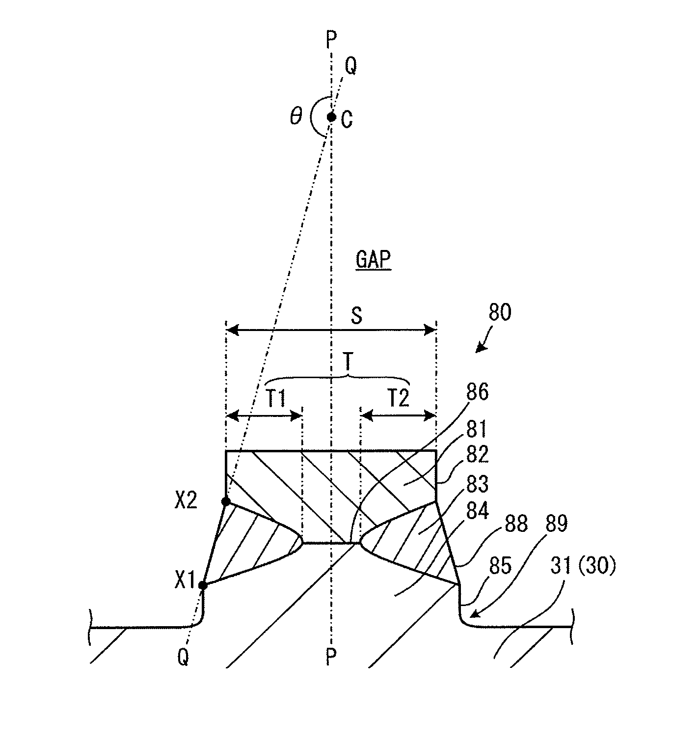
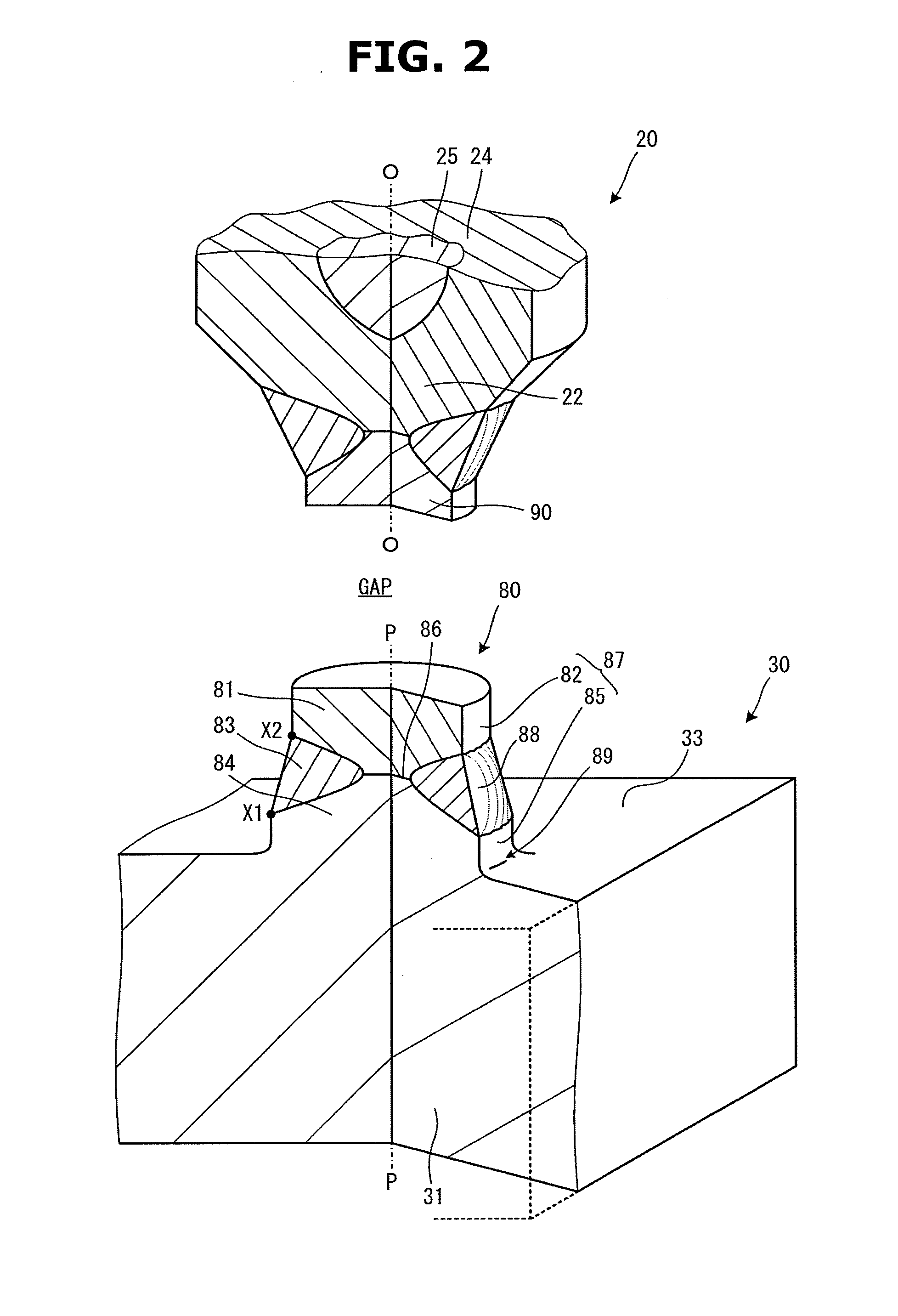
[0014]In the spark plug of the present invention, the melting portion is formed throughout the entire circumference of the ignition portion. That is, the discharge portion and the pedestal portion are held inwards in the radial direction by the melting portion, at sections where the discharge portion and the melting portion, and the pedestal portion and the melting portion are arranged in strata in the radial direction of the ignition portion. Therefore, when the discharge portion and the pedestal portion extend (deform) in the radial direction when subjected to heat, this extension is restrained or suppressed by their resistance to expansion towards radially outward. The resistance is contributed by the annular melting portion formed continuously in the circumferential direction of the ignition portion. Here, when viewing the profile line shape of the cross section of the ignition portion, the melting portion has a configuration that connects the side surface of the pedestal portion and the side surface of the discharge portion. Because of this, as compared with a case where the melting portion connects the side surface of the discharge portion and a plane that spreads out along the radial direction of the ignition portion (e.g. one side surface of the ground electrode or a top end surface of the pedestal portion), it is possible to lessen the restraint on the extension in the outward direction of the radial direction of the discharge portion by the melting portion.
[0019]In the spark plug of the configuration 3, when the discharge portion and the pedestal portion extend (deform) in the radial direction when subjected to heat, difference of the internal stress occurring at each interface between the discharge portion, the pedestal portion and the melting portion is limited, and unbalanced internal stresses can be suppressed, thereby suppressing the occurrence of the crack or the separation more effectively.
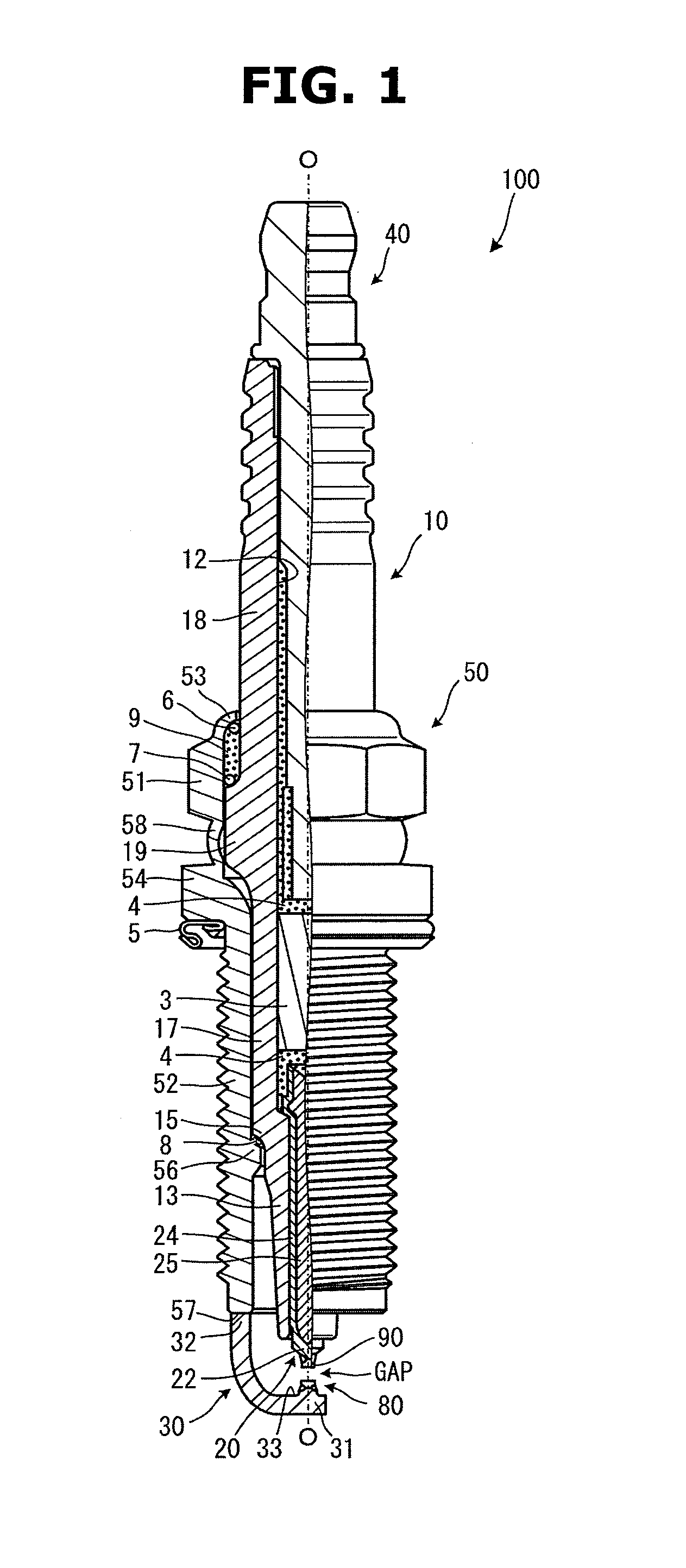
[0020]In the spark plug of the configuration 4, because the ignition portion is formed so as to protrude from the one side surface of the ground electrode, when building up a root portion of the ignition portion by providing the root portion with the first connecting portion, even in a case where the ignition portion is subjected to vibrations etc. due to engine drive, a structure that can sufficiently stand the load due to the vibrations can be obtained.
[0021]Furthermore, in the spark plug of the configuration 5, in the case where the flange portion is formed at the pedestal portion, stability of junction of the pedestal portion with the one side surface of the ground electrode can be increased. Then when building up the pedestal portion by providing the second connecting portion between the flange portion and the side surface of a body of the pedestal portion, a structure by which the ignition portion can sufficiently stand the load such as the vibrations imposed on its root portion can be obtained, same as the configuration 4, and this is desirable.
[0022]Moreover, in the spark plug of the configuration 6, forming the discharge portion, which forms the spark discharge gap between the center electrode and the discharge portion, using the noble metal or the noble metal alloy is favorable for obtaining resistance to oxidation and resistance to spark erosion.

Problems solved by technology

In such spark plug, because a great thermal load is applied to the electrode chip, there is a risk that a crack or separation will appear at a junction portion between the discharge portion and the ground electrode.

Method used


Image

  • Spark plug
  • Spark plug
  • Spark plug

Examples


embodiment 1

[0056]Evaluation test was conducted to verify the effect by providing the definition to the configuration of the melting portion 83 formed at the ignition portion 80 provided on the ground electrode 30 of the spark plug 100. First, evaluation concerning a relationship between the degree of inclination (inclination by the exterior angle θ) of the exposure surface 88 of the melting portion 83 and separation resistance and a relationship between the difference in the linear expansion coefficient of the constituent material between the discharge portion 81 and the pedestal portion 84 which form the ignition portion 80 and the separation resistance, was carried out. In this evaluation test, four different materials made of noble metal alloy, respectively having 8.3, 9.7, 10.4 and 13.4 (×10−6) [1 / K] as the linear expansion coefficient at 1000° C., were prepared, and the discharge portion whose outside diameter S is set to 0.7 mm was made for each material. Further, the ground electrode wa...

embodiment 2

[0064]Next, evaluation concerning a relationship between the extending length (the forming depth) of the melting portion 83 in the inward direction of the radial direction and the separation resistance, was carried out. In this evaluation test, two different discharge portions whose outside diameters S are set to 0.7 mm and 1.2 mm were made using material made of Pt alloy having 10.4×10⁻⁶ [1 / K] as the linear expansion coefficient at 1000° C. Further, the ground electrode was made using Ni alloy whose linear expansion coefficient at 1000° C. is 17.8×10⁻⁶ [l / K], and the pedestal portion was formed through the pressing working of the inner surface of the ground electrode. Furthermore, the discharge portion was set on the pedestal portion, and the laser beam was radiated from the side of both portions toward the junction or joining surface between both portions to join both portions together by the laser welding around the circumference thereof. Then evaluation samples (samples) of the ...


PUM


Abstract

The present invention provides a spark plug which is capable of suppressing a occurrence of crack and separation by determining a structural configuration of a melting portion formed in a junction portion between a discharge portion and a pedestal portion which form an ignition portion that protrudes from a ground electrode. In a profile line shape of a cross section including a center axis P of an ignition portion 80, an exposure surface 88 of a melting portion 83 connects a side surface 82 of a discharge portion 81 and a side surface 85 of a pedestal portion 84. Further, an exterior angle θ formed between an imaginary line Q, which passes through a boundary position X1 between the melting portion 83 and the pedestal portion 84 and a boundary position X2 between the melting portion 83 and the discharge portion 81, and the center axis P at a node C, satisfies 135°≦θ≦175°. Furthermore, a proportion T / S of a forming depth T of the melting portion 83 to an outside diameter S of the discharge portion 81 satisfies T / S≧0.5.

Description

CROSS REFERENCE TO RELATED APPLICATIONS[0001]This application is a National Stage of International Application No. PCT / JP2010 / 000447, filed on Jan. 27, 2010, which claims priority from Japanese Patent Application No. 2009-018643, filed on Jan. 29, 2009, the contents of all of which are incorporated herein by reference in their entirety.TECHNICAL FIELD[0002]The present invention relates to a spark plug whose ground electrode is provided with an acicular ignition portion that forms a spark discharge gap with a center electrode.BACKGROUND ART[0003]In recent years, intensification of environmental pollution control measure against exhaust gas exhausted from an internal combustion engine has been required. Since enhancement of ignitability (ignition performance) contributes to purification of the exhaust gas, a spark plug whose ground electrode is provided with, on an inner surface thereof, an electrode chip (a discharge portion) that is formed using noble metal having high resistance to...

Claims


Application Information

Patent Timeline
Patent Type & Authority Patents(United States)
IPC IPC(8): H01T13/20
CPCH01T13/39H01T13/32
Inventor MIYASHITA, NAOMICHIMUSASA, MAMORUSUZUKI, AKIRATORII, KAZUYOSHIKATO, TOMOAKI
Owner NGK SPARK PLUG CO LTD
Why Eureka
Try Eureka