Crossmember and manufacturing method for crossmember

a manufacturing method and crossmember technology, applied in the direction of superstructure subunits, vehicle components, understructures, etc., can solve the problems of increasing the number of parts, the thickness dimension of the remaining part (a part to which a relatively small load is applied), and the limit of reducing the weight of the vehicle body, so as to reduce the strength of the welding location (joining parts) and increase the manufacturing cost. , the effect of reducing the strength

Active Publication Date: 2020-03-12
TOYOTA JIDOSHA KK
View PDF0 Cites 5 Cited by
  • Summary
  • Abstract
  • Description
  • Claims
  • Application Information

AI Technical Summary

Benefits of technology

[0007]However, when the crossmember 60 is manufactured as described above, the number of parts increases, and the structure may become complex. Also, since welding is necessary at a plurality of places, manufacturing cost may be increased, heat damages may happen at welding locations (a reduction in strength at the welding locations), and rust may be generated (rust may be generated in surrounding areas of the welding locations). Further, since strength of the welding locations (joining parts) is reduced (strength is lowered in comparison with a case where the separated structure is not used), there is a limit in reducing the thickness dimensions (the thickness dimensions of the panels 71, 73). As a result, there is a limit in reducing a weight of the crossmember 60.
[0008]The disclosure provides a vehicle body crossmember and a manufacturing method for the crossmember by which a weight reduction is possible while simplifying a structure and reducing welding locations due to a reduction of the number of parts.

Problems solved by technology

Therefore, the remaining part (a part to which a relatively small load is applied) has an unnecessarily large thickness dimension.
Thus, with the manufacturing method according to the foregoing related art, there is a limit in reducing a weight of a vehicle body by reducing a weight of a crossmember.
However, when the crossmember 60 is manufactured as described above, the number of parts increases, and the structure may become complex.
Also, since welding is necessary at a plurality of places, manufacturing cost may be increased, heat damages may happen at welding locations (a reduction in strength at the welding locations), and rust may be generated (rust may be generated in surrounding areas of the welding locations).

Method used


Image

  • Crossmember and manufacturing method for crossmember
  • Crossmember and manufacturing method for crossmember
  • Crossmember and manufacturing method for crossmember

Examples


Embodiment Construction

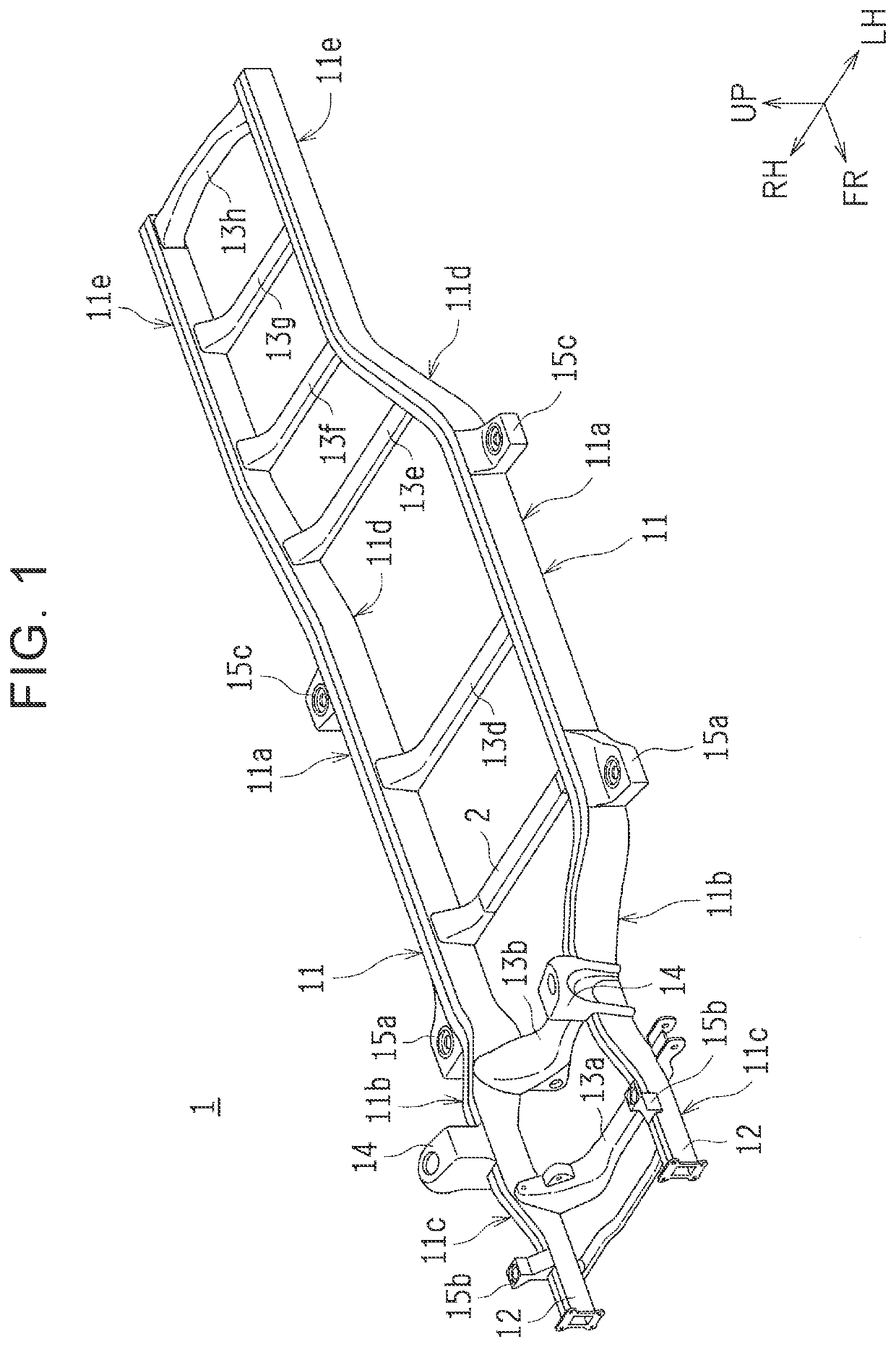
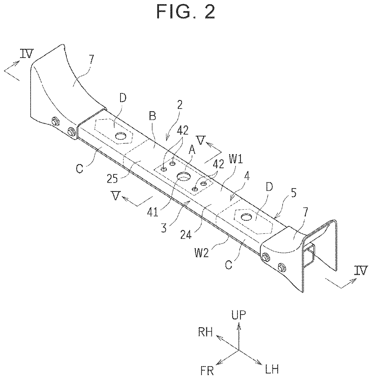
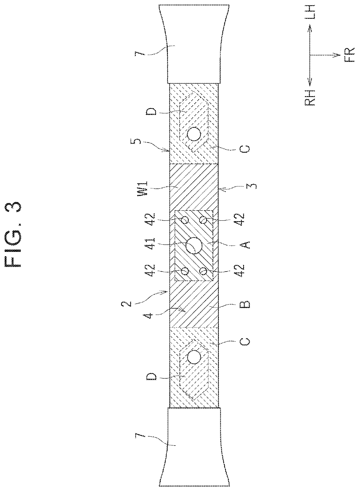
[0036]Hereinafter, an embodiment of the disclosure is described with reference to the drawings, in the embodiment, a case is described where the disclosure is applied to a crossmember of a vehicle body frame that is configured as a so-called ladder frame.

[0037]Outline of Structure of Vehicle Body Frame

[0038]FIG. 1 is a perspective view of a vehicle body frame 1 according to an embodiment, in FIG. 1, an arrow FR represents a vehicle body front direction, an arrow UP represents an upper direction, an arrow RH represents a vehicle body right direction, and an arrow LH represents a vehicle body left direction.

[0039]As shown in FIG. 1, the vehicle body frame 1 is provided with a pair of right and left side rails 11 that extend in a vehicle body front-rear direction on both outer sides in a vehicle width direction, respectively. Each of the side rails 11 has a closed section structure and is provided with an intermediate portion 11a, a front kick-up portion 11b, a front portion 11c, a rea...


PUM


Abstract

A crossmember and a manufacturing method for a crossmember is disclosed. The crossmember is made of a metal sheet having a given sectional shape, configures a part of a vehicle body frame, extends along a vehicle width direction, and has an engine mount attaching portion provided in a part of an upper plate portion. The crossmember has an upper crossmember that is made of a single metal sheet extending along the vehicle width direction, the upper crossmember having a larger thickness in a region including the engine mount attaching portion of the upper plate portion and a surrounding area of the engine mount attaching portion compared to a thickness of a remaining region.

Description

CROSS-REFERENCE TO RELATED APPLICATIONS[0001]This application claims priority to Japanese Patent Application No. 2018-167486 filed on Sep. 7, 2018, which is incorporated herein by reference in its entirety including the specification, drawings and abstract.BACKGROUND1. Technical Field[0002]The disclosure relates to a crossmember and a manufacturing method for a crossmember.2. Description of Related Art[0003]As a vehicle body frame, a structure including a pair of right and left side rails (also referred to as side frames) extending in a vehicle body front-rear direction and a crossmember that bridges between the side rails is known (referred to as a frame structure). In general, the crossmember is made into a given section structure (for example, a closed section structure) by, for example, pressing a metal sheet (a high-tensile steel plate and so on), and thus obtains high rigidity.[0004]Japanese Unexamined Patent Application Publication No. 2004-352022 (JP 2004-352022 A) discloses...

Claims


Application Information

Patent Timeline
Patent Type & Authority Applications(United States)
IPC IPC(8): B62D21/03B62D25/20
CPCB62D21/03B62D25/2036B62D21/02B62D21/07
Inventor ASAI, TETSUYAOKUMOTO, RYUICHI
Owner TOYOTA JIDOSHA KK
Why Eureka
Try Eureka