Voice coil and electrodynamic speaker using same

A voice coil and coil technology, applied in the direction of sensors, electrical components, etc., can solve the problems of increased weight of the speaker vibration system, insufficient transmission of the speaker vibration plate, poor sound reproduction ability, etc., and achieve the effect of preventing deformation.

Active Publication Date: 2011-06-01
ONKYO KK
View PDF6 Cites 8 Cited by
  • Summary
  • Abstract
  • Description
  • Claims
  • Application Information

AI Technical Summary

Problems solved by technology

[0010] However, in the case of a slender dynamic speaker in which the short diameter direction is shorter than the long diameter direction, including a planar coil arranged so that the winding axis direction of the coil is perpendicular to the vibration direction of the speaker diaphragm, for example, there is In the case of a plate-shaped driving force transmission member as in Document 1, problems such as an increase in the weight of the speaker vibration system, a decrease in the magnetic flux density of the linear magnetic gap, and a decrease in the reproduction efficiency of the speaker for reproducing sound tend to occur.
On the other hand, for example, in the case where there is no plate-shaped driving force transmission member as in Patent Document 4, there is a problem that the driving force acting on the portion arranged on the magnetic gap of the magnetic circuit of the flat coil is The rigidity of the flat coil is insufficient, and the vibration plate of the speaker joined to the flat coil cannot be sufficiently transmitted, and the high-pass cutoff frequency is lowered, and a sufficient sound reproduction frequency band cannot be secured. As a result, it becomes an electrodynamic speaker with poor sound reproduction ability

Method used


Image

  • Voice coil and electrodynamic speaker using same
  • Voice coil and electrodynamic speaker using same
  • Voice coil and electrodynamic speaker using same

Examples


Embodiment 1

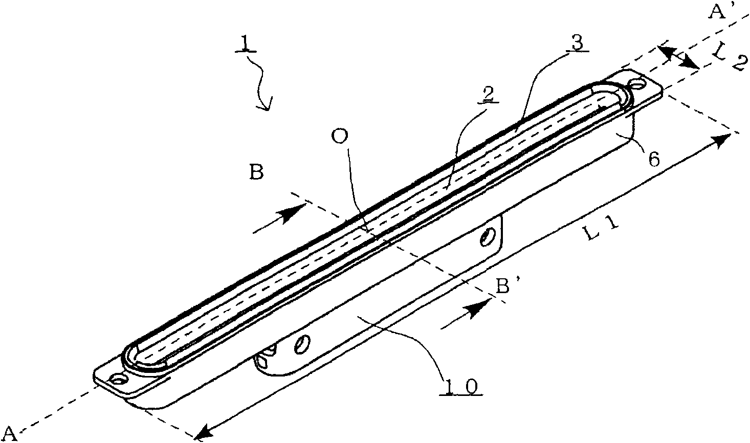
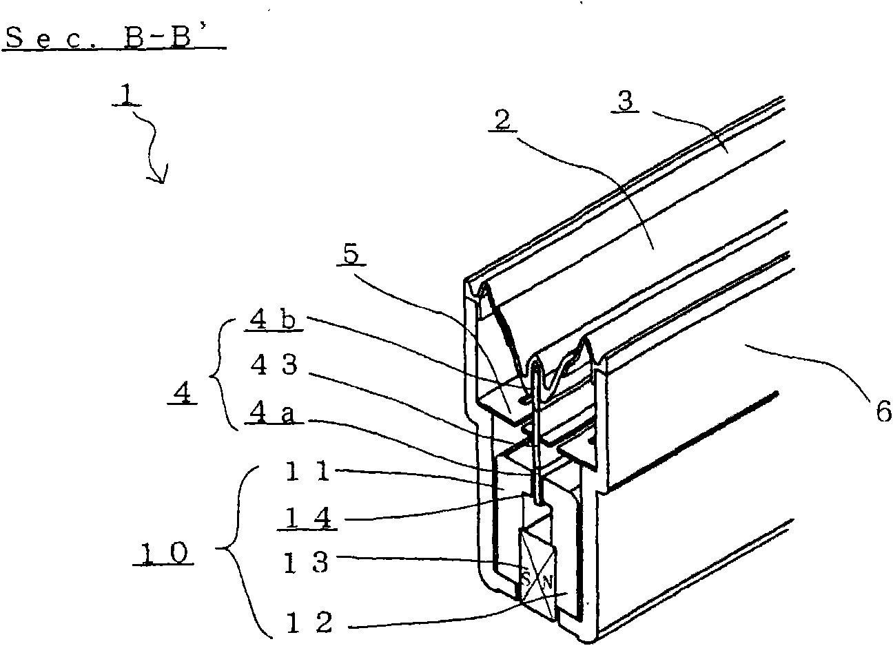
[0051] figure 1 and figure 2 It is a figure explaining the dynamic speaker 1 which concerns on the preferred embodiment of this invention. in addition, image 3 It is a figure explaining the voice coil 4 which is a preferable embodiment of this invention. Specifically, figure 1 It is the perspective view which looked at the dynamic speaker 1 from the front side, figure 2 It is a partial enlarged view of the section in the short-diameter direction of the dynamic speaker 1 . image 3 (a) is a side view of the voice coil 4 viewed from the short diameter direction, image 3 (b) is a C-C' sectional view of the voice coil 4, image 3 (c) is a perspective view of the voice coil 4, image 3 (d) is a developed view illustrating the structure of the voice coil 4 . In addition, as will be described later, a part of the structure and internal structure of the dynamic speaker 1 is omitted. In addition, the direction in which the straight line (major axis) connecting the points...

Embodiment 2

[0064] Figure 4 It is a diagram illustrating another coil 4A that can constitute the dynamic speaker 1 instead of the coil 4 of the previous embodiment, and it is different from that of the previous embodiment. image 3 (b) Corresponding C-C' profile. The coil 4A of the present embodiment has the same structure as the coil 4 of the previous embodiment, includes two air-cored coils 41a and 42a and a reinforcing plate 43a described later, and is flat-shaped and has approximately the same external dimensions. . Among them, the coil 4A has a dimension 41r of the inner peripheral end of one air-core coil 41a forming the racetrack-shaped inner peripheral end 4e, a dimension 42r of the inner peripheral end of the other air-core coil 42a, and a reinforcement plate. The thickness 43t of 43a and the dimension of the outer peripheral edge part 43e of the reinforcement board 43a differ from the coil 4 of the previous Example in the point that the thickness 43t differs. Therefore, the ...

Embodiment 3

[0069] Figure 5 It is a diagram illustrating another coil 4B that can constitute the dynamic speaker 1 instead of the coil 4A of the previous embodiment, and is the same as that of the previous embodiment. Figure 4 Comparable C-C' profile. The coil 4B of the present embodiment has the same structure as the coil 4A of the previous embodiment, includes two air-cored coils 41a and 42a and a reinforcing plate 43b described later, and has approximately the same external dimensions and is flat-shaped. the coil. In the coil 4B, the size 41r of the inner peripheral end of one air-core coil 41a forming the racetrack-shaped inner peripheral end 4e is different from the size 42r of the inner peripheral end of the other air-core coil 42a. The point of forming the fitting step portion of the inner peripheral end portion 4e is the same as that of the coil 4A of the previous embodiment. On the other hand, the shape of the reinforcing plate 43b of the coil 4B is different from that of th...


PUM


Abstract

The invention provides a voice coil and an electrodynamic speaker. The electrodynamic speaker uses the tabulate voice coil in scroll direction vertical to the vibrating direction of a speaker vibration plate and is long and thin with short diameter being smaller than the long diameter. The electrodynamic speaker has superior voice reproduction capacity and is suitable for being mounted on equipment such as a display. The voice coil is formed by bonding end surfaces of the first and second coils as the tabulate hollow coils by way of making the first coil and second coils consistent with respective scrolls and connecting the bonded first and second coils in series or in parallel by way of flowing voice signal current in a same direction. The hollow coil is formed by winding the flat wire in multiple layers in a non-staggered manner relative to the scrolls and comprises a reinforcing board which is accommodated in an internal peripheral space regulated by an internal peripheral end part formed by bonding the first and second coils. The internal peripheral end part is matched with the external peripheral end part.

Description

technical field [0001] The present invention relates to an elongated voice coil and an electrodynamic speaker in which the short diameter direction is shorter than the long diameter direction. In particular, it relates to a voice coil which is excellent in sound reproduction capability and is suitable for mounting on devices such as monitors, and an electrodynamic speaker using the voice coil. Background technique [0002] Conventionally, in audio equipment such as a display in which a speaker for reproducing sound is mounted, the space required for mounting the speaker has been required to be reduced in size. In particular, in the case of an electrodynamic speaker that requires a slim shape, there is a limit to a slim shape due to the structure of the magnetic circuit. In addition, the slender (rectangular, oblong (including elliptical, racetrack)) dynamic speaker, when using the speaker with a limited vibration plate area in the short diameter direction and a high magneti...

Claims


Application Information

Patent Timeline
Patent Type & Authority Applications(China)
IPC IPC(8): H04R9/04H04R9/06
Inventor 藤谷武士森山裕介丰福健一郎小岛义生吴伟
Owner ONKYO KK
Why Eureka
Try Eureka