Star-handle system for locking antenna to a vehicle roof

a technology for roofs and antennas, applied in the field of roof antennas, can solve the problems of insufficient sealing function, achieve the effect of optimizing the sealing function, fast installation, and simplifying the installation of the antenna

Active Publication Date: 2014-02-13
HIRSCHMANN CAR COMMUNICATION
View PDF5 Cites 9 Cited by
  • Summary
  • Abstract
  • Description
  • Claims
  • Application Information

AI Technical Summary

Benefits of technology

[0005]The object of this invention is therefore to improve this generic roof antenna with regard to its installation method and its configuration, in particular, with the aim of further simplifying its installation.
[0006]This object is achieved the attachments are provided in the form of a central threaded pivot pin that projects into the interior of the vehicle and a star handle that interacts with the pivot pin after the roof antenna has been mounted in its preinstallation position. This star handle, which in an especially advantageous embodiment includes precisely four arms extending at right angles to each other, is located initially in a preinstallation position. This means that the star handle is mounted in such a way relative to the roof antenna and also relative to the roof opening so as to allow it to be passed together with its attachments vertically from above toward the interior. This means that the roof antenna—or more precisely, its base plate or a seal mounted on the base plate or other elements—comes to rest on the upper face of the roof, and that it then becomes possible to manipulate the star handle to enable it to be moved from its preinstallation position (preattachment) to its final installation position after it has been preattached by the detent tabs that also project vertically downward through the roof opening. In other words, the roof antenna is placed from above onto the roof and passed together with its detent tabs and attachments through the roof opening. Once the roof antenna has come to rest on the upper face of the roof such that preattachment has been effected by the detent tabs, the attachment, that is, the star handle, can be manipulated to mount the roof antenna in its final position on the roof of the vehicle in a permanent, perfectly positioned, and immovable manner. The rotation of the star handle on the threaded central pivot pin has the advantage of allowing fast installation to be effected, optionally without tools. In addition, the force with which the base plate comes to rest on the vehicle roof can be adjusted very precisely by rotating the star handle. This is advantageous, in particular, if a seal is provided between the lower face of the base plate and the top surface of the roof. This effectively allows the seal to optimally perform its seal function, thereby avoiding a situation in which the sealing function is not sufficient due to inadequate compression of the seal, or also is not optimal due to excessive compression. The advantage is furthermore provided that any tolerances can be compensated for, in particular, in the varying thickness of the roof. As a result, the roof antenna according to the invention also allows for very flexible installation in different vehicles with various roof thicknesses.
[0007]In a development of the invention, the star handle is provided in such form as to allow it to be passed with the ends of the arms in a preinstallation position vertically through an opening in the roof, then gripping by the arm ends under the lower face of the roof in its final installation position. Fastening the roof antenna to the roof of a vehicle by the arm ends of the star handle enables a very good lever action to be achieved, thereby resulting in a strong force by which the antenna is fastened to the roof of the vehicle. The sides and / or surfaces of these arm ends facing the lower face of the roof can be beveled so as to facilitate installation. It is furthermore possible for the surface of the star handle facing toward the lower face of the roof to include tangs, ridges, or the like when the handle is in its final installation position. Even if the star handle and the central pivot pin are composed of an electrically conductive material, these means can also function to effect the ground connection for the roof antenna even if the vehicle roof is also composed of a metallic material. If these elements are not composed of a metallic material, an approach can be considered whereby the ground connection is implemented using other elements, for example, plug connectors.
[0008]In a development of the invention, at least one stop is provided on the base plate to limit the angle of rotational travel of the star handle. This at least one stop, preferably one limit stop for the preinstallation position and one limit stop for the final installation position, has the advantage of delimiting a range of motion for the star handle to facilitate installation of the roof antenna. The star handle is thus especially advantageously moved only between these two stops that define the respective starting position and end position. As a result, the mounting torque of the roof antenna on the roof of the vehicle can also be set at a predefined value.
[0009]In a development of the invention, at least one guide rib is provided on the base plate, preferably, two opposing guide ribs or two guide ribs that are oriented at right angle to each other. These guide ribs that point vertically downward from the base plate, that is, toward the roof opening of the vehicle, have the advantage of matching the shape of the roof opening, and provide guidance and alignment for the roof antenna both during preinstallation and final installation. This at least one guide rib is advantageously integrated as one piece with the base plate (for example, guide rib and base plate are composed of a plastic injection-molded unit) or are additionally either detachably or permanently joined to the base plate.
[0010]In a development of the invention, the star handle in its preinstallation position covers the at least one plug connector, then exposes it in the final installation position. A critical advantage here is the fact that the star handle is moved to a preinstallation position whereby preferably each one of its arms covers one plug connector. In this delivery configuration of the roof antenna, the plug connectors are protected against being damaged or contaminated, the plug connectors typically being provided in the form of female sockets. It is only after the roof antenna has been fastened in a preattached manner to the roof and the star handle has been moved from its preinstallation position to its final installation position for final installation that the star handle exposes the at least one plug connector, thereby enabling the plug connector of the roof antenna to be plugged into the mating plug connector, for example, at the end of a cable when the roof antenna has been permanently mounted to the roof of the vehicle in its specified position.

Problems solved by technology

This effectively allows the seal to optimally perform its seal function, thereby avoiding a situation in which the sealing function is not sufficient due to inadequate compression of the seal, or also is not optimal due to excessive compression.

Method used


Image

  • Star-handle system for locking antenna to a vehicle roof
  • Star-handle system for locking antenna to a vehicle roof
  • Star-handle system for locking antenna to a vehicle roof

Examples


Embodiment Construction

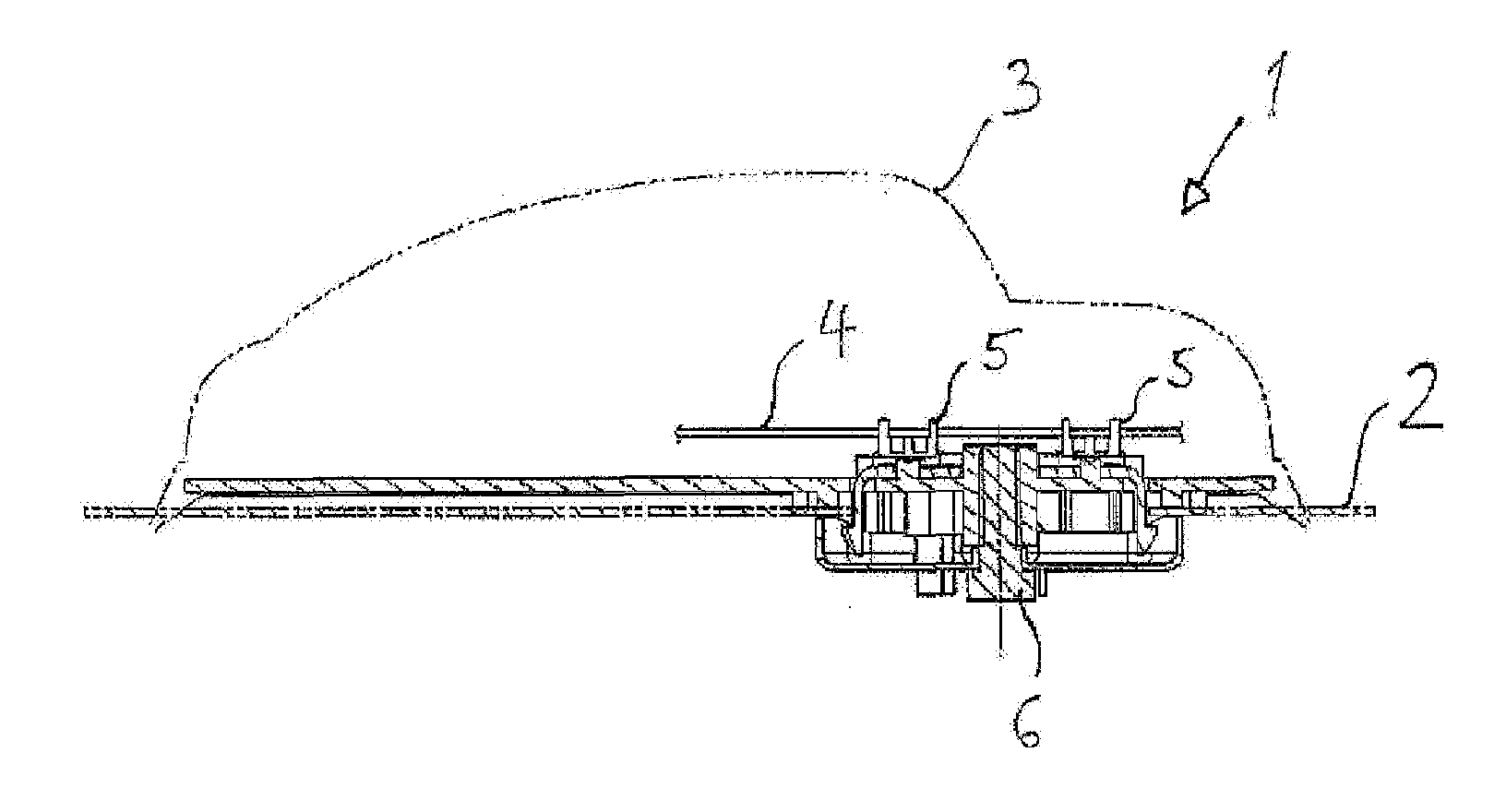
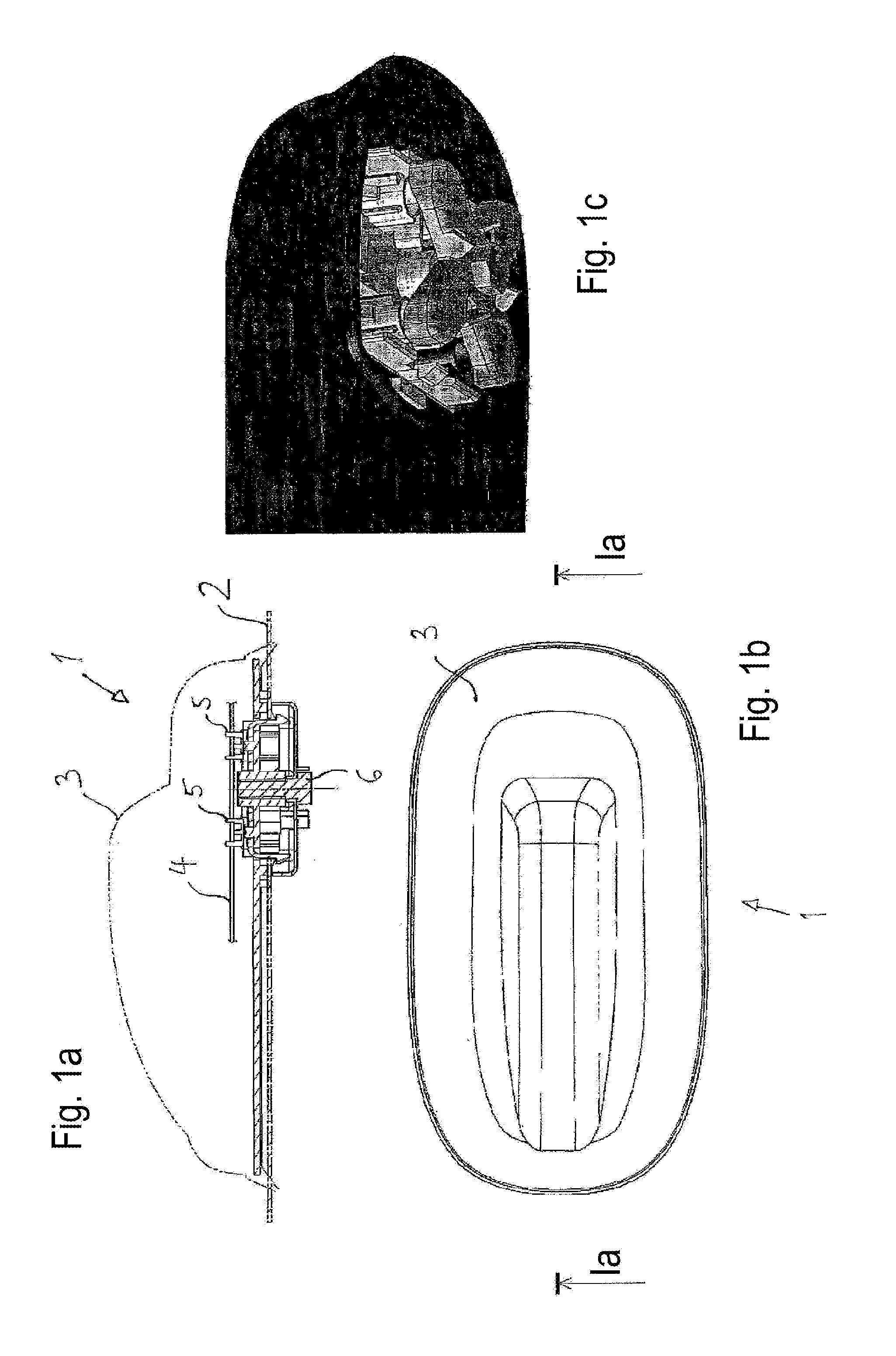
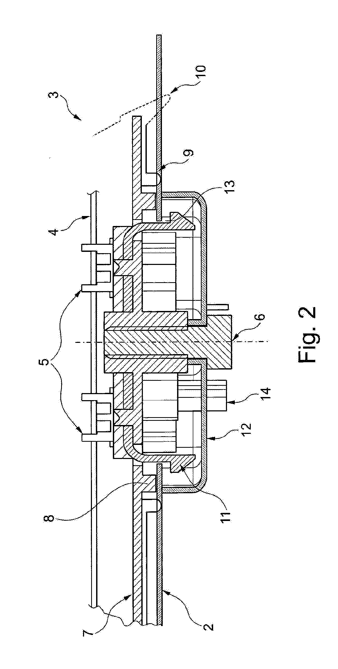
[0018]FIGS. 1a through 4b are, to the extent details are illustrated, different views of a roof antenna 1 to be installed on a roof 2 of a vehicle. FIG. 1a shows the antenna 1 installed in on the roof 2. In terms of function, this antenna 1 comprises an antenna cover 3, where, for example, a circuit board 4 including unillustrated antenna elements (for example, for telephone, GPS, TV, and the like) are accommodated under the cover 3. This circuit board 4 can include downwardly directed plug connectors 5 (or also only one plug connector), although it does not necessarily have to include the at least one plug connector. Establishing the connections of the antenna elements under the cover 3 to attached electronic devices can also be effected by other means, such as, for example, cables. In addition, a central pivot pin 6 is shown in this view. In FIG. 1b, the antenna 1 is viewed from above, while in FIG. 1c it is seen from below, the following discussion referencing FIGS. 2 through 4b ...


PUM


Abstract

The invention relates to a roof antenna (1) for mounting on a roof (2) of a vehicle, said roof antenna (1) having a base plate (7) and an antenna cover (3) that can be connected to the base plate (7). A printed circuit board (4) with antenna elements and at least one plug connection (5) is arranged under the antenna cover (3). The base plate (7) has detent hooks (11) for pre-attaching on the roof (2) and fixing means for a final assembly, said fixing means being designed as a central dome (6) with a screw thread and a star handle (12) that interacts with the dome (6).

Description

CROSS REFERENCE TO RELATED APPLICATIONS[0001]This application is the U.S.-national stage of PCT application PCT / EP2012 / 058244 filed 4 May 2012 and claiming the priority of German patent application 102011100473.8 itself filed 4 May 2011.FIELD OF THE INVENTION[0002]The invention relates to a roof antenna for installation on a roof of a vehicle and comprising comprises a base plate and an antenna cover that can be attached to the base plate as well as a circuit board including antenna elements and at least one plug connector under the antenna cover, the base plate having detent tabs for preattachment to the roof and an attachment for final installation.BACKGROUND OF THE INVENTION[0003]A wide variety of embodiments of a roof antenna and corresponding methods for installing this type of roof antenna on the roof of a vehicle have been disclosed (for example in DE 10 2005 041 473, U.S. Pat. No. 7,436,367, or U.S. 2006 / 0077110).[0004]The generic reference DE 10 2012 202 677.0, which has no...

Claims


Application Information

Patent Timeline
Patent Type & Authority Applications(United States)
IPC IPC(8): H01Q1/32
CPCH01Q1/3275H01Q1/1214
Inventor GERNETH, CHRISTIANSILVA, DAVID
Owner HIRSCHMANN CAR COMMUNICATION
Why Eureka
Try Eureka