Mid-foot fixation plate

a technology for fixing plates and mid-foot, which is applied in the field of plates for fixing bones and joints, can solve the problems of joint degeneration and even damage to adjacent nerves and blood vessels, severe fractures and/or dislocations, and non-union of mid-foot arthrodesis attempts, so as to reduce the prominence of plates, reduce bone fractures, and accurately conform to local anatomy

Inactive Publication Date: 2008-03-18
BIOMET CV
View PDF13 Cites 80 Cited by
  • Summary
  • Abstract
  • Description
  • Claims
  • Application Information

AI Technical Summary

Benefits of technology

[0008]In a further preferred feature, four additional screw holes are defined at the interior of the plate to increase the number of points of attachment of the plate to the bones of the mid-foot or to increase the ability to stabilize multiple bone segments in the case of a difficult mid-foot fracture. The four additional screws are oriented within the perimeter defined by the six screws formed in the protrusions.
[0011]The protrusions and cut-outs help reduce not only the prominence of the plate, but also the material requirements. The plate is also formed at a minimal thickness that still retains the ability to stabilize the fusion site. In a preferred embodiment, the plate has a thickness of less than 1.0 mm. In order to more accurately conform to the local anatomy, the plate is defined at a spherical curvature, which is preferably at a fixed radius.
[0012]One benefit of the fixation plate of the present invention is that it is much more versatile than prior devices for achieving fusion of the mid-foot. A further benefit is that the plate offers a plurality of options for bone screw placement to stabilize the mid-foot bones and joints, accomplish firm reduction of bone fractures and ultimately ensure union and / or fusion.

Problems solved by technology

Trauma to the mid-foot often results in severe fractures and / or dislocations.
Failure to treat a significant Lisfranc injury may result in joint degeneration and even damage to the adjacent nerves and blood vessels.
However, this form of fixation frequently results in non-union in mid-foot arthrodesis attempts, possibly because the bone fragments and / or joints cannot be sufficiently immobilized by pins, screws or staples alone.

Method used


Image

  • Mid-foot fixation plate
  • Mid-foot fixation plate
  • Mid-foot fixation plate

Examples


Embodiment Construction

[0019]For the purposes of promoting an understanding of the principles of the invention, reference will now be made to the embodiments illustrated in the drawings and described in the following written specification. It is understood that no limitation to the scope of the invention is thereby intended. It is further understood that the present invention includes any alterations and modifications to the illustrated embodiments and includes further applications of the principles of the invention as would normally occur to one skilled in the art to which this invention pertains.

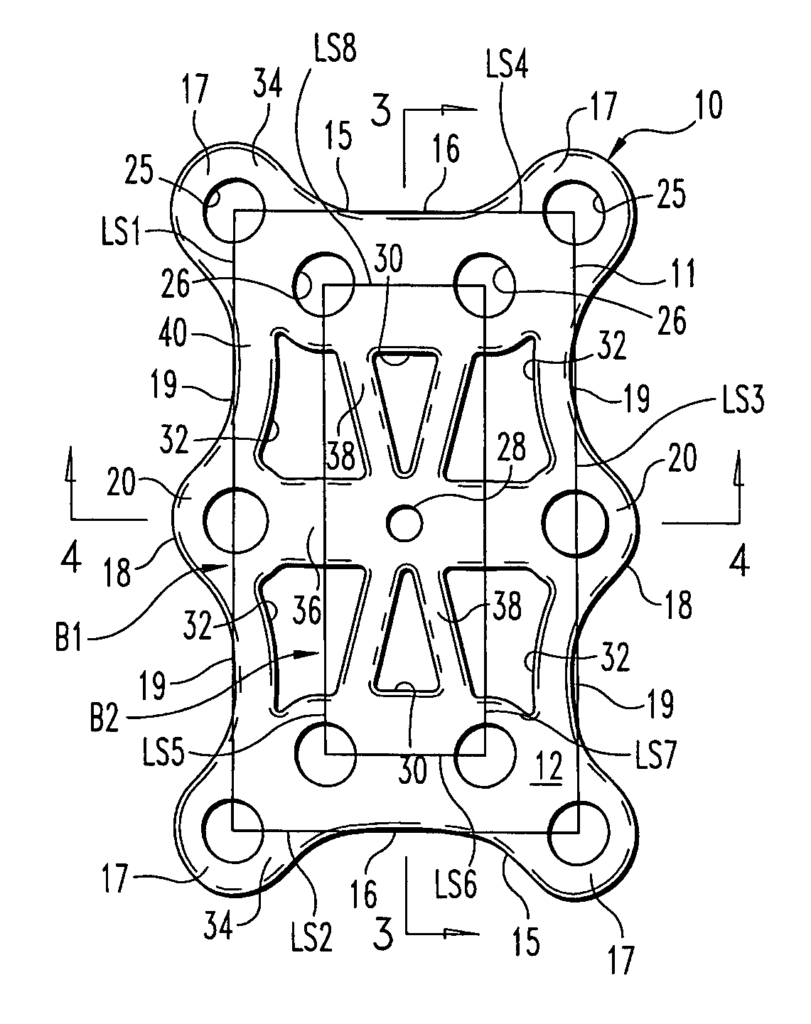
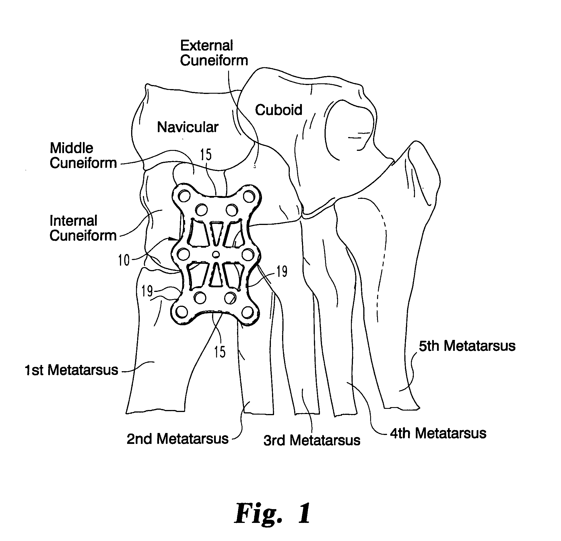
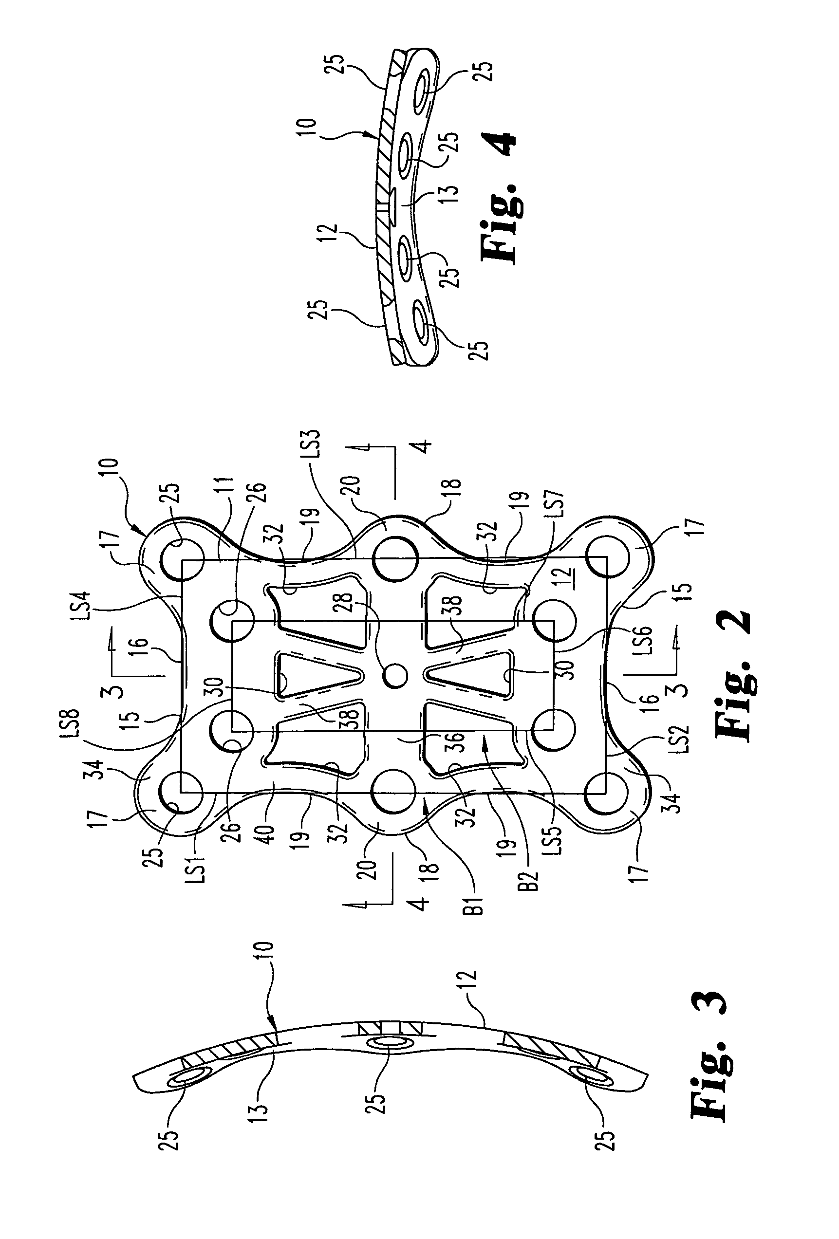
[0020]The bones of the mid-foot are illustrated from the dorsal aspect in FIG. 1, along with a fixation plate 10 in accordance with a preferred embodiment of the invention. As can be seen in the figure, the plate 10 spans between the base of the first and second metatarsal bones across to the internal (or medial) and middle cuneiforms. In the embodiment illustrated in FIG. 1, the plate 10 is provided that permit...


PUM


Abstract

A fixation device for fixation and / or fusion of the bones and joints of the mid-foot includes a plate having a plurality of screw holes for attachment of the plate around the perimeter of the fusion site. Four screw holes are positioned at the corners of the plate and two screw holes are located at the opposite sides and mid-length of the plate. Four additional screw holes are defined at the interior of the plate to increase the number of points of attachment of the plate to the bones of the mid-foot or to increase the ability to stabilize multiple bone segments in the case of a difficult mid-foot fracture. The plate includes a plurality of cut-outs defined between or interior of the screw holes.

Description

BACKGROUND OF THE INVENTION[0001]The present invention relates to plates for fixation of bones and joints. More specifically, the invention pertains to a fixation plate configured for fixation of the mid-foot.[0002]Trauma to the mid-foot often results in severe fractures and / or dislocations. One such trauma is the well-known Lisfranc injury, which was named after the French doctor who first described the injury during the Napoleonic Wars. The injury identified by Dr. Lisfranc occurred when a horseman fell from the horse with his / her foot caught in the stirrup. The resulting trauma was a fracture of multiple bones of the mid-foot with dislocation of the fragments. In modern times, a Lisfranc injury indicates an injury to the normal alignment of the cuneiforms and metatarsal joints with the loss of their normal spatial relationships. Injuries of this type may occur when a heavy item falls on the mid-foot or from stepping into a small hole and then falling with a twisting imparted to t...

Claims


Application Information

Patent Timeline
Patent Type & Authority Patents(United States)
IPC IPC(8): A61B17/58
CPCA61B17/8061A61B17/8085Y10S606/906
Inventor MYERSON, MARKPRASAD, PRIYASANDERS, ROYBREMER, CHRIS
Owner BIOMET CV
Why Eureka
Try Eureka