

Radio device and electronic apparatus
a radio device and electronic equipment technology, applied in the direction of elongated active element feed, resonant antenna, independent non-interacting antenna combinations, etc., can solve the problems of reducing performance, and reducing the service life of dipole antennas
- Summary
- Abstract
- Description
- Claims
- Application Information
AI Technical Summary
Benefits of technology
Problems solved by technology
Method used
Image

Examples
first embodiment
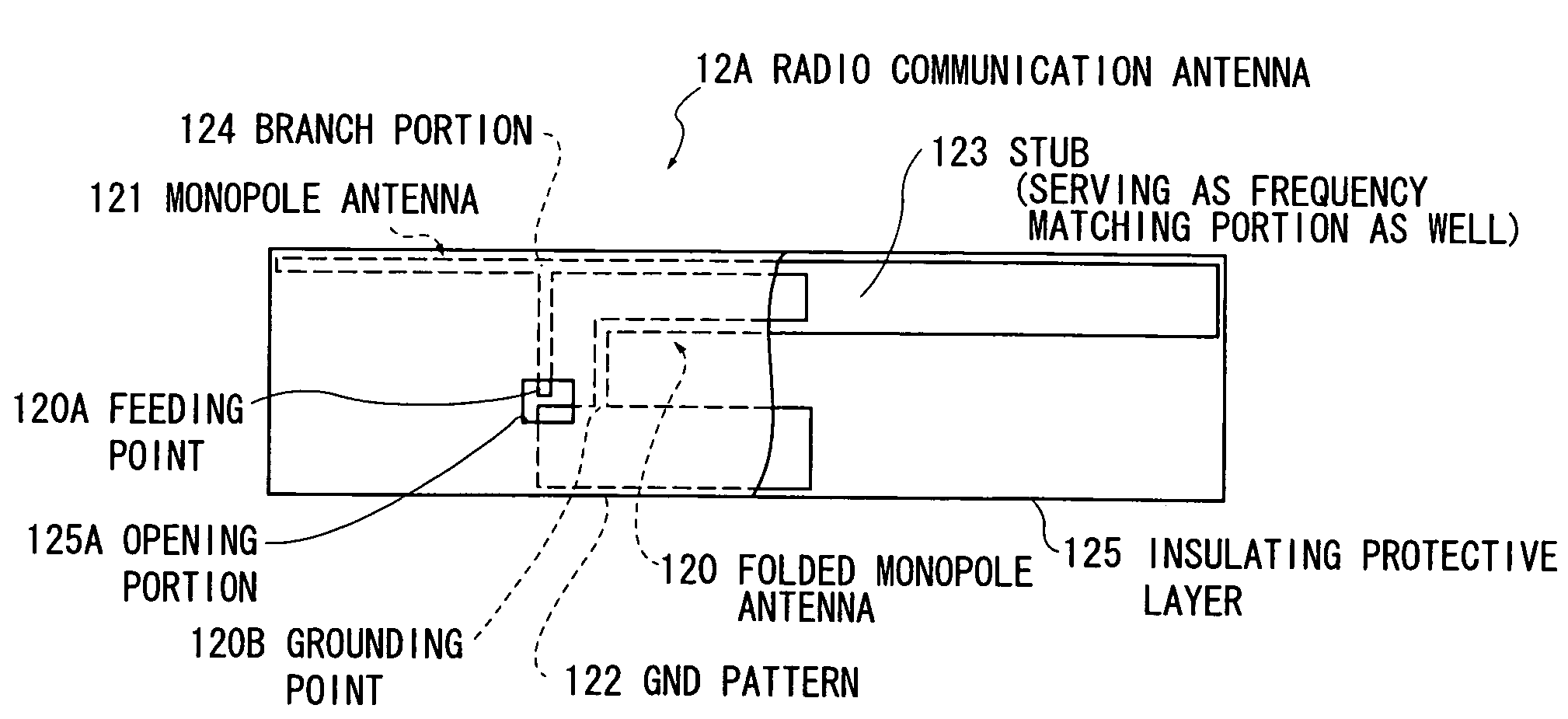
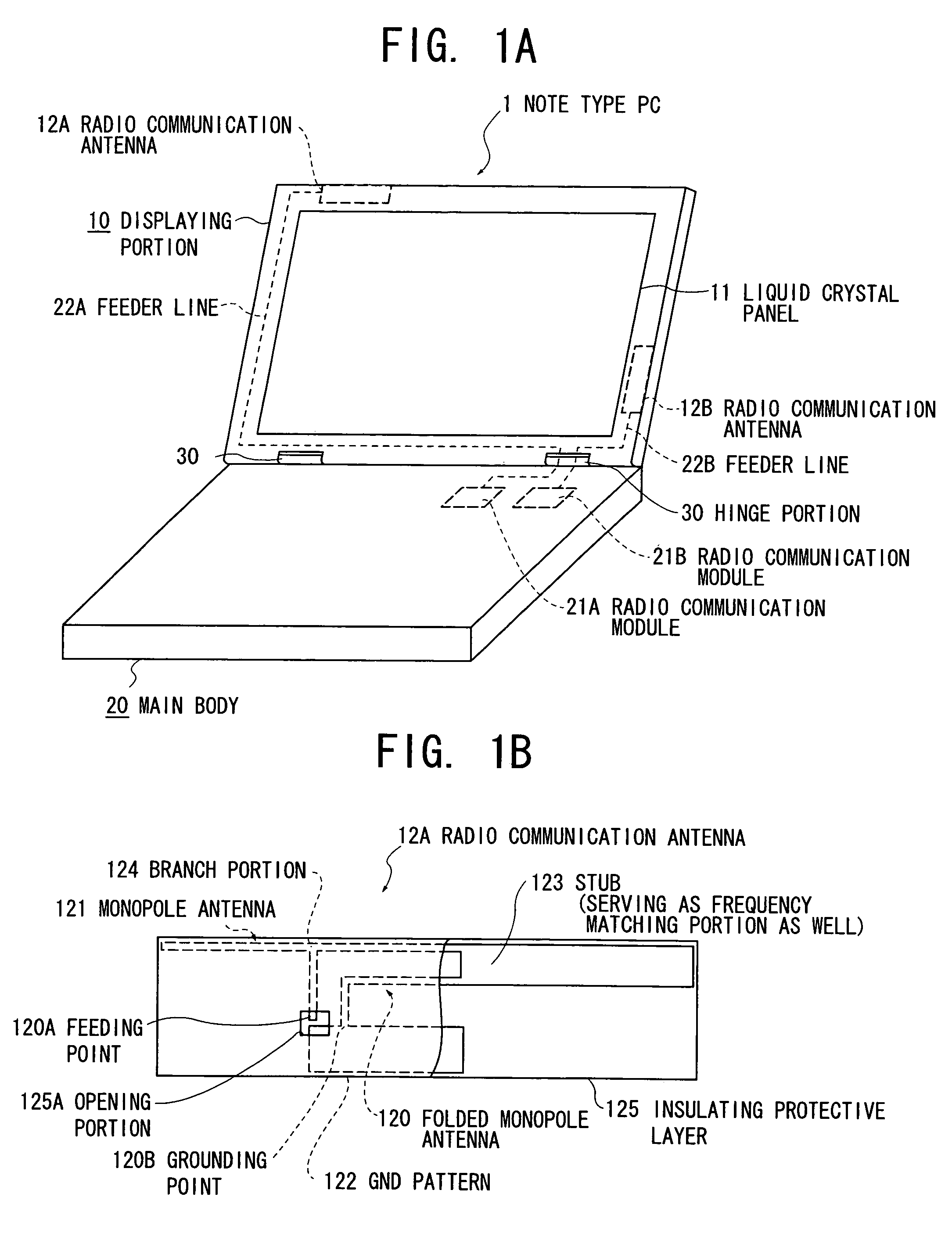
[0031]FIGS. 1A and 1B are respectively a perspective view showing a note type personal computer (PC) as an electronic apparatus according to a first embodiment of the present invention, and a plan view showing a radio communication antenna accommodated in an envelope case of a displaying portion of the note type PC shown in FIG. 1A
Construction of Note Type PC 1
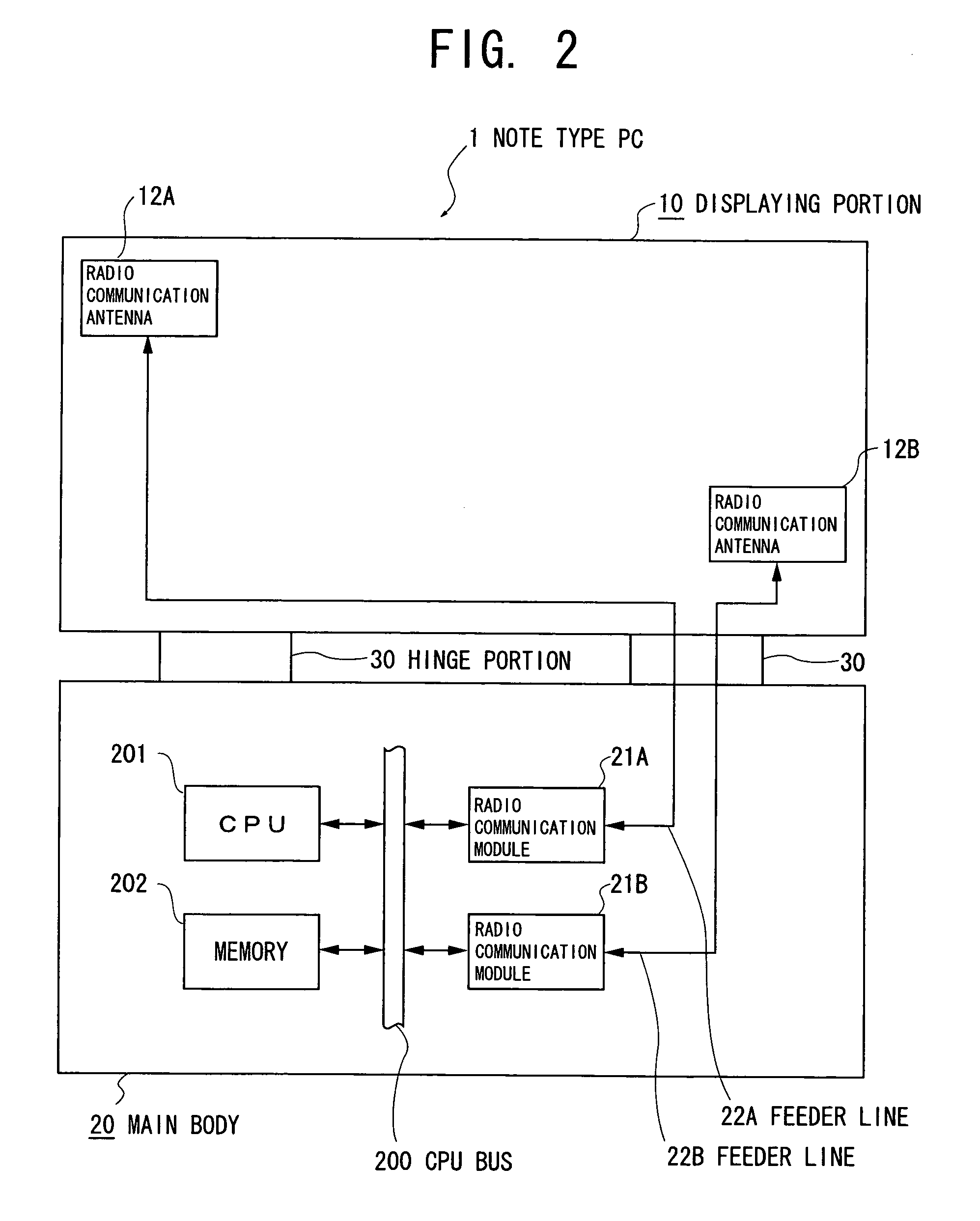
[0032]A note type PC 1, as shown in FIG. 1A, is constituted by a displaying portion 10 and a main body 20 when being roughly classified. In the first embodiment, the displaying portion 10 is a liquid crystal display device having a liquid crystal panel 11, and has radio communication antennas 12A and 12B in an upper portion and a side portion of the liquid crystal panel 11, respectively. In addition, the display portion 10 and the main body 20 are openably and closeably constructed.
[0033]The main body 20 has radio communication modules 21A and 21B as power supply circuits each of which serves to generate a high-frequency signa...
second embodiment
[0048]FIG. 3 is a plan view showing a radio communication antenna according to a second embodiment of the present invention. At that, in the following description, the portions having the same constructions and functions as those of the first embodiment are designated with the same reference numerals, respectively.
[0049]The radio communication antenna 12A has a construction in which the frequency matching portion 126 described in the first embodiment is provided as an extension from the outward path of the folded monopole antenna 120. With this construction, the outward path of the folded monopole antenna 120 and the frequency matching portion 126 have the same width and are disposed in one straight line.
[0050]According to the second embodiment described above, provision of the frequency matching portion equal in straight line to the outward path portion in the folded monopole antenna 120 results in that even when there is a disposition restriction in the mounting region of the ante...
third embodiment
[0053]FIGS. 4A, 4B and 4C are respectively a plan view showing a radio communication antenna according to a third embodiment of the present invention, a plan view showing a construction in which a meander portion shown in FIG. 4A is provided on a stub side, and a plan view showing a construction in which the meander portion shown in FIG. 4A is provided on a head side of a frequency matching portion.
[0054]The radio communication antenna 12A has a construction in which a portion 127 folded in meander-like shape (hereinafter referred to as “a meander portion 127”) is added to the frequency matching portion 126 described in the second embodiment. With this construction, the outward path of the folded monopole antenna 120 and the frequency matching portion 126 are formed with the same width. Alternatively, the meander portion 127 can be provided on a side near the stub 123 as shown in FIG. 4B, or can be provided on a side away from the stub 123 as shown in FIG. 4C.
[0055]According to the ...
PUM
 Abstract
Description
Claims
Application Information