Method and apparatus for detecting heat sink faults

a heat sink and fault technology, applied in the field of cooling systems, can solve the problems of cpu overheating, cpu temperature rise, and failure to properly install and operate a heat sink

Inactive Publication Date: 2008-03-18
GOOGLE LLC
View PDF8 Cites 19 Cited by
  • Summary
  • Abstract
  • Description
  • Claims
  • Application Information

AI Technical Summary

Problems solved by technology

Proper installation and functioning of a heat sink can be critical.
A faulty or improperly mounted heat sink can, therefore, cause the CPU to overheat.
Even when a cooling system is functioning as the designer intended, a CPU may require throttling, which reduces CPU temperature by adding idle cycles to instruction pipelines.
For example, when swapping out a bad CPU, adding a second CPU, or replacing a planar / motherboard, a user risks damaging or improperly reinstalling the heat sink.
Even when merely inspecting a heat sink, the user may unintentionally disturb or contaminate the thermal grease, or drop the heat sink and damage its vapor chamber seal, each of which may cause a fault by interfering with proper heat transfer between the CPU and the heat sink.
Present methods and systems are not optimally designed to detect or diagnose overheating problems.
For example, some systems measure temperature of the CPU and signal cooling problems only after the CPU has already overheated.
Once the CPU has overheated, it may have already failed, potentially resulting in irrecoverable data loss and the expense of replacing the CPU.
Additionally, systems that detect an overheating CPU do not typically identify the specific cause, such as failure of the heat sink.

Method used


Image

  • Method and apparatus for detecting heat sink faults
  • Method and apparatus for detecting heat sink faults
  • Method and apparatus for detecting heat sink faults

Examples


Embodiment Construction

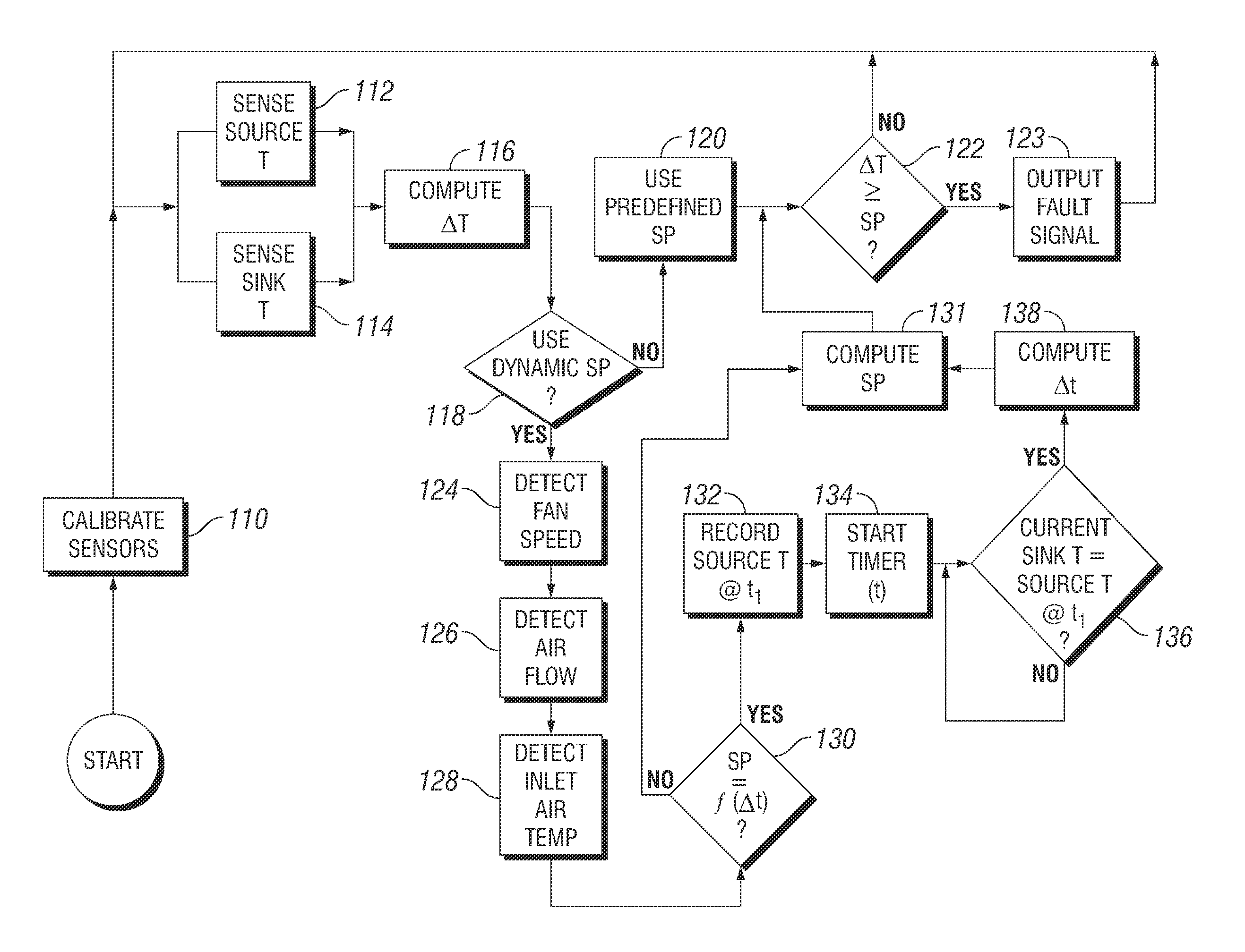
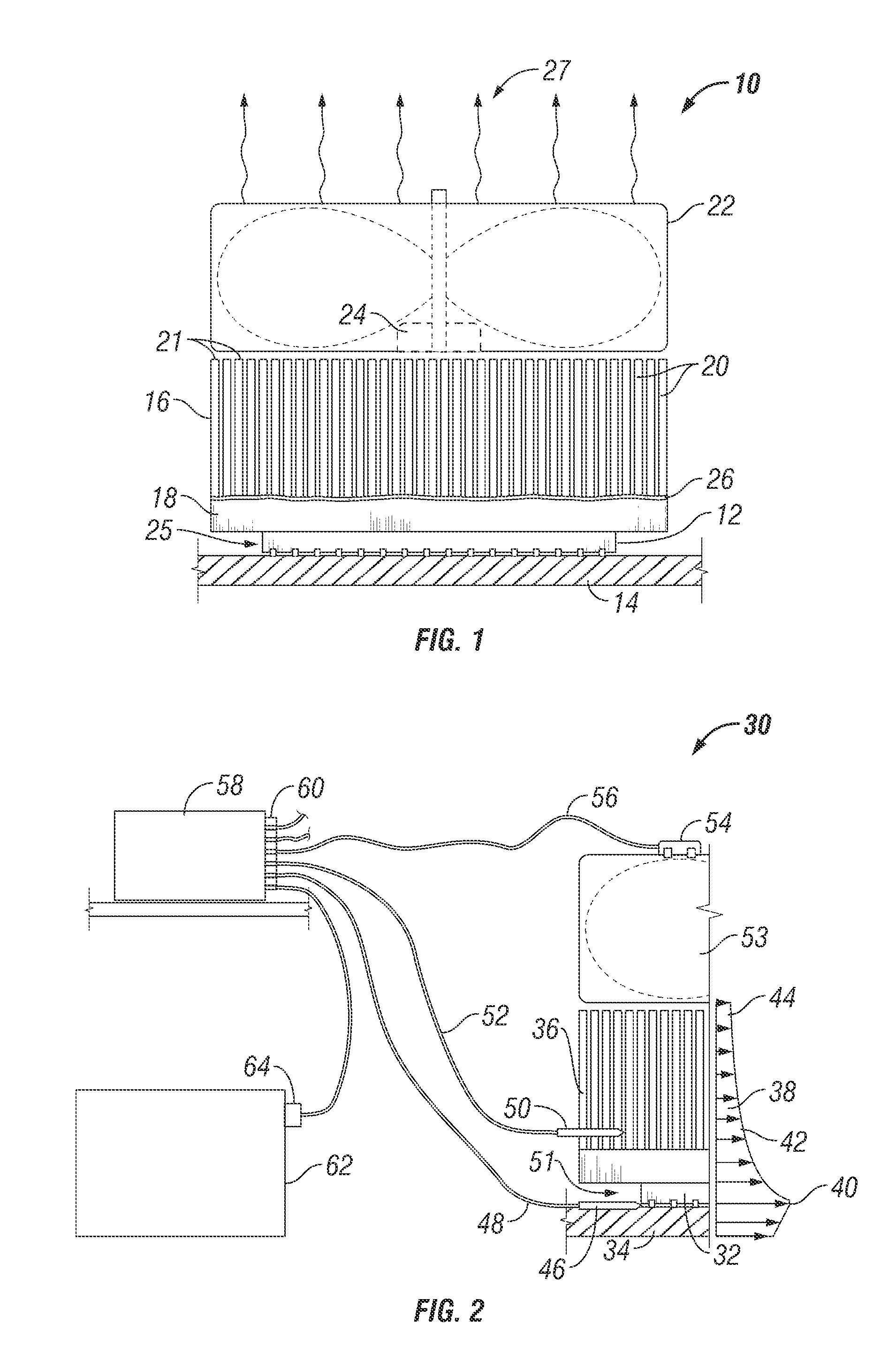
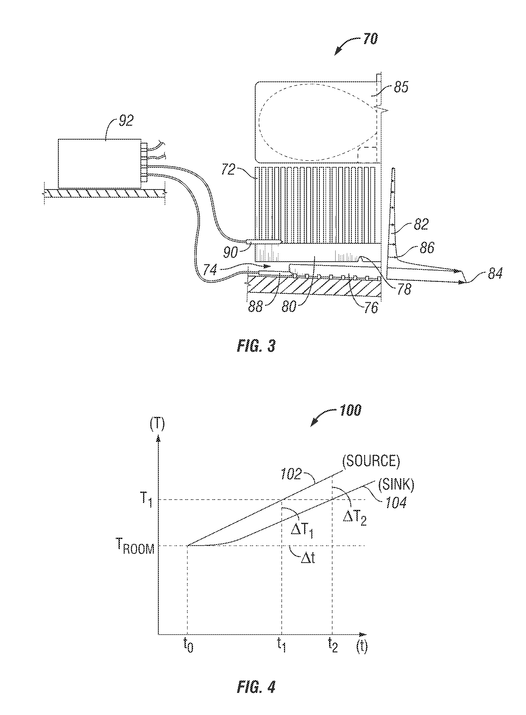
[0016]Systems and methods are disclosed for detecting cooling system faults. Accordingly, overheating of heat-generating components may be detected or anticipated prior to failure of the heat-generating component or other component being cooled. The cause of overheating may also be diagnosed, such as by identifying a specific component of the cooling system that is responsible. When a heat sink is properly mounted, thermal resistance and corresponding heat transfer between a heat source and a heat sink is predictable. If the heat source and heat sink are contained in a predefined environment, the temperature differential between the heat source and the heat sink is predictable. A faulty or improperly mounted heat sink will therefore be indicated by an abnormal temperature differential under relevant operation conditions. The systems and methods according to the invention may be adapted for use with a variety of electronic systems. Embodiments of the invention are particularly well s...


PUM

PropertyMeasurementUnit
temperatureaaaaaaaaaa
source temperatureaaaaaaaaaa
sink temperatureaaaaaaaaaa

Abstract

Detecting, predicting, and diagnosing faults in a cooling system. According to one embodiment, a heat sink is in thermal contact with a heat-generating electronic component. When a temperature differential between the electronic component and the heat sink exceeds a set point, a fault signal is generated. The set point may be empirically or theoretically determined. The set point may be a static set point, or it may be a dynamic set point determined according to real-time operational parameters of the system. The system may be implemented with predictive failure analysis (PFA) to provide a more reliable, efficient, inexpensive, and robust computer system.

Description

BACKGROUND OF THE INVENTION[0001]1. Field of the Invention[0002]The present invention relates to cooling systems for electronic components.[0003]2. Description of the Related Art[0004]It is important to properly cool heat-generating electronic components. In a computer, for example, a cooling system is typically used to keep the CPU at a safe operating temperature. Such a cooling system generally includes a heat sink for dissipating heat from the CPU. Proper installation and functioning of a heat sink can be critical. Modern servers have very little thermal design margin. A faulty or improperly mounted heat sink can, therefore, cause the CPU to overheat. Even when a cooling system is functioning as the designer intended, a CPU may require throttling, which reduces CPU temperature by adding idle cycles to instruction pipelines.[0005]There are numerous opportunities over the course of a computer's useful life for a user to inadvertently cause a heat sink fault. For example, when swapp...

Claims


Application Information

Patent Timeline
Patent Type & Authority Patents(United States)
IPC IPC(8): G01K17/00G06F15/00
CPCG06F11/24
Inventor BASHOR, PAUL DOUGLASMCMILLAN, HENRY GAINESPURRINGTON, CHALLIS LLEWELLYNSCOLLARD, MICHAEL LEOSTANKEVICH, VICTOR A.
Owner GOOGLE LLC
Why Eureka
Try Eureka