
Apparatus employing predictive failure analysis based on in-circuit FET on-resistance characteristics

a technology of in-circuit fet and resistance, applied in reliability/availability analysis, resistance/reactance/impedence, instruments, etc., can solve problems such as the likely failure of the semiconductor, and achieve the effect of minimizing downtim

Inactive Publication Date: 2006-11-23
GOOGLE LLC
View PDF12 Cites 5 Cited by
  • Summary
  • Abstract
  • Description
  • Claims
  • Application Information

AI Technical Summary

Benefits of technology

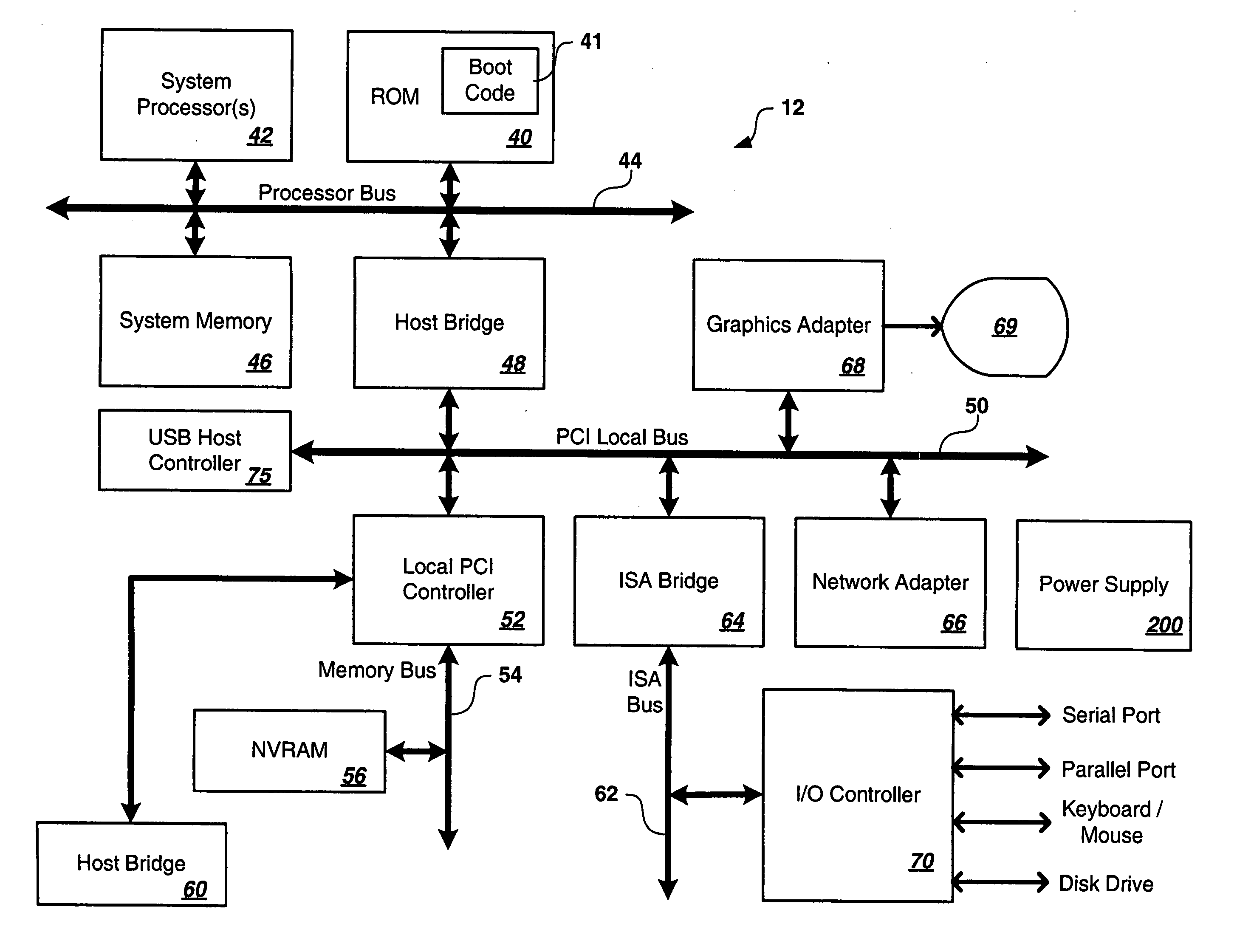
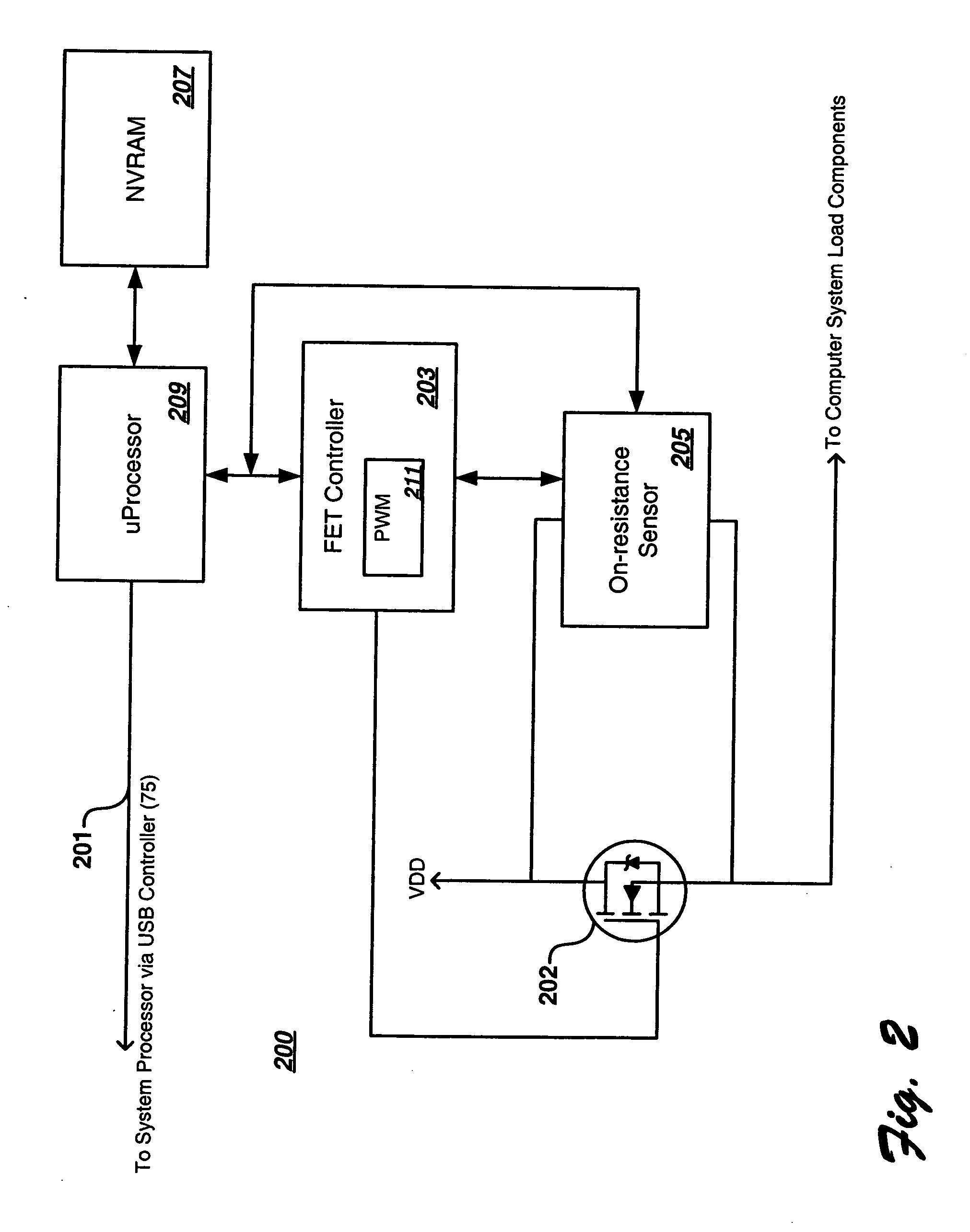
[0010] It has been discovered that the aforementioned challenges are addressed using a system and method which monitor the on-resistance of a semiconductor over a period of time. The time period of interest preferably corresponds to the life of the semiconductor or over as large of a time span as practical in a given design or scenario. Other time periods are accommodated. The monitored semiconductor is typically a semiconductor which either sources or sinks current to or from components of an apparatus. The on-resistance is measured in-circuit during normal operations of the apparatus, thus minimizing downtime. The apparatus and method predict that the semiconductor is likely to fail based on the monitored on-resistance and report a predictive failure to the apparatus based on the prediction.

Problems solved by technology

Additionally, what are needed are apparatus and methods which additionally isolate a failure before the failure is able to do additional circuit damage.
The apparatus and method predict that the semiconductor is likely to fail based on the monitored on-resistance and report a predictive failure to the apparatus based on the prediction.

Method used


Image

  • Apparatus employing predictive failure analysis based on in-circuit FET on-resistance characteristics
  • Apparatus employing predictive failure analysis based on in-circuit FET on-resistance characteristics
  • Apparatus employing predictive failure analysis based on in-circuit FET on-resistance characteristics

Examples


Embodiment Construction

[0025] While the present invention will be described more fully hereinafter with reference to the accompanying drawings, in which a preferred embodiment of the present invention is shown, it is to be understood at the outset of the description which follows that persons of skill in the appropriate arts may modify the invention here described while still achieving the favorable results of this invention. Accordingly, the description which follows is to be understood as being a broad, teaching disclosure directed to persons of skill in the appropriate arts, and not as limiting upon the present invention.

[0026] Referring now more particularly to the accompanying drawings, in which like numerals indicate like elements or steps throughout the several views, a preferred embodiment of the present invention will be described. Reference throughout this specification to “one embodiment,”“an embodiment,” or similar language means that a particular feature, structure, or characteristic describ...


PUM


Abstract

A computing system includes a semiconductor which sources / sinks current to / from components within the system, an in-circuit semiconductor on-resistance characterization circuit which measures the on-resistance of the semiconductor, and a processor which periodically or continuously engages the characterization circuit over the life of the semiconductor to obtain a series of on-resistance measurements. Depending on the type of semiconductor used, or depending on arbitrary design limitations, the computing system predicts semiconductor failure based on either a relative mode or an absolute mode. The relative mode is useful when using FET's since on-resistance values vary significantly. In the relative mode, an optional NVRAM is used to store one or more on-resistance measurements which may serve as a reference for assuring proper circuit operation within tolerable deviations from the reference. In the absolute mode, one or more optional thresholds are utilized to assure that circuit operation remains in a known good region.

Description

CROSS-REFERENCE to RELATED APPLICATIONS [0001] The present application is related to co-pending, commonly assigned, application Ser. No. 10 / 855,122 (attorney docket number RPS920040095US1) having common inventorship, filed May 27, 2004, and entitled “Apparatus Having In-circuit FET On-resistance Characterization.” The related application is hereby incorporated by reference herein in its entirety.[0002] BACKGROUND of the INVENTION [0003] This invention pertains to high availability computing systems and other systems which are able to benefit from predictive failure analysis and, more particularly, to a computer system which predicts the failure of a circuit in the system based on on-resistance values which are derived while the system is fully operational. [0004] High availability systems require a minimum of downtime. Any scheduled downtime is used to update system components which cannot be updated during normal system operation such as BIOS, operating system patches, and low-leve...

Claims


Application Information

Patent Timeline
IPC IPC(8): G01R25/00G01R27/00
CPCG06F11/008
Inventor BANDHOLZ, JUSTIN POTOK
Owner GOOGLE LLC
Learn More