Method and apparatus to determine the wind speed and direction experienced by a wind turbine

a wind turbine and wind speed measurement technology, applied in wind energy generation, wind motors with perpendicular air flow, liquid fuel engine components, etc., can solve the problems of not providing a direct method of measuring the mean wind speed and direction experienced by the centre of the wind turbine's rotor, and measuring is placed. problem, to achieve the effect of low cos

Active Publication Date: 2008-03-25
ROMO WIND AG
View PDF7 Cites 34 Cited by
  • Summary
  • Abstract
  • Description
  • Claims
  • Application Information

AI Technical Summary

Benefits of technology

[0016]A third aspect of the current invention is to provide a wind speed and direction sensing method for wind turbines which can measure both wind speed and direction with a simple, robust and low cost apparatus.
[0032]Using the phase and extreme values of the sinusoidal relationship results in a simple method which requires low computing power.

Problems solved by technology

The problem with this approach is that the wind measurement is placed behind the rotor.
However, in many locations this is not the case.
This is very costly because another mast needs to be erected at the position of the wind turbine.
However, since the rotor is spinning and the wind sensor needs to be kept stationary, a complex mechanical system needs to be built into the rotor in order to allow the rotor to spin about the stationary shaft holding the wind sensor.
However, no details are provided of how the sinusoidal output is used to orient the wind turbine.
However, the three systems described above do not provide a direct method of measuring the mean wind speed and direction experienced by the centre of the wind turbine's rotor.
Sensors mounted in or on the blades are both difficult to install and to maintain due to their position.
Sensors mounted on the blades also experience the problem that the air speed over the blade is to a large extent a function of the blade speed.
Furthermore, the three systems described above do not give any information as to the flow inclination angle of the wind.

Method used


Image

  • Method and apparatus to determine the wind speed and direction experienced by a wind turbine
  • Method and apparatus to determine the wind speed and direction experienced by a wind turbine
  • Method and apparatus to determine the wind speed and direction experienced by a wind turbine

Examples


Embodiment Construction

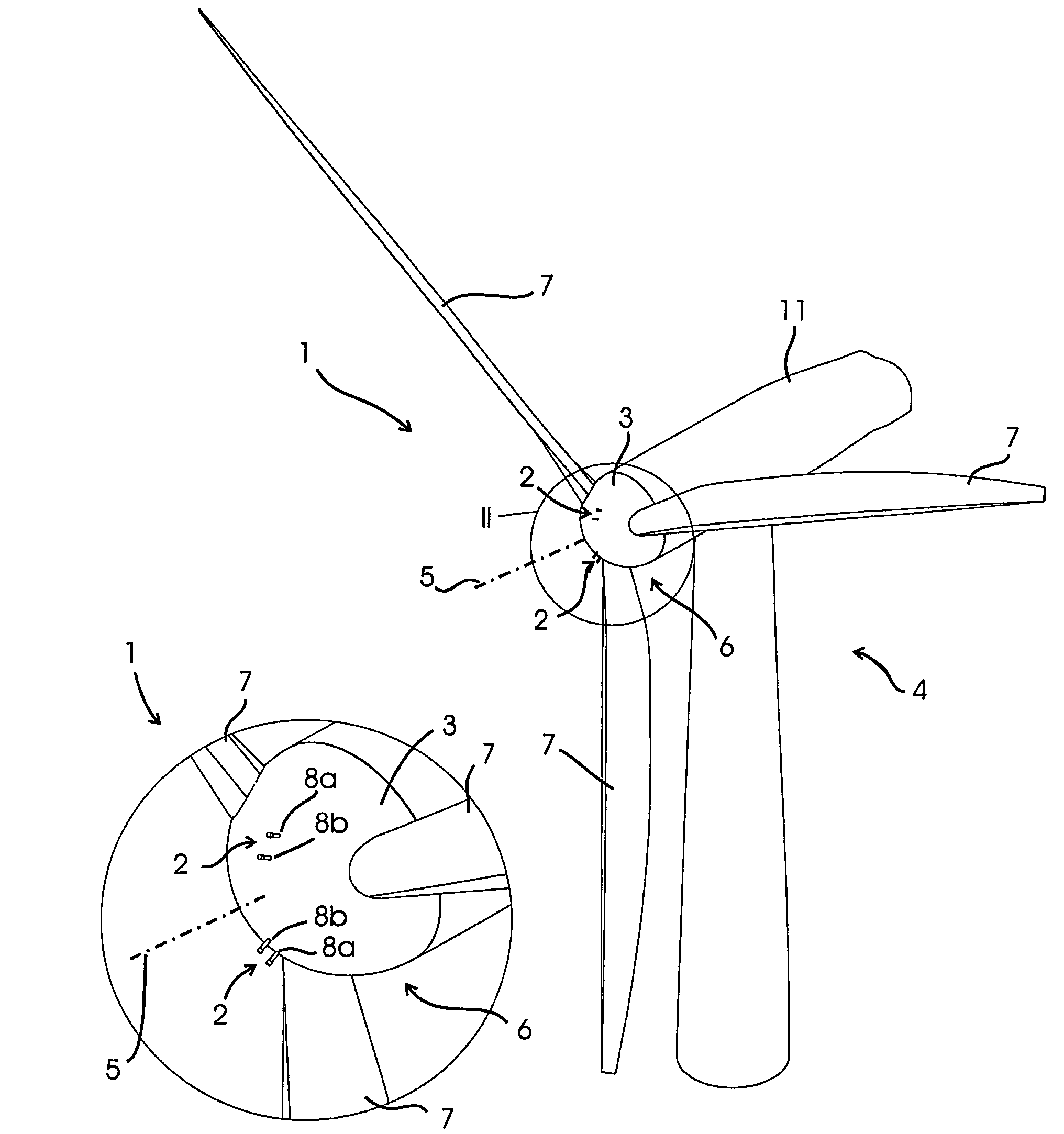
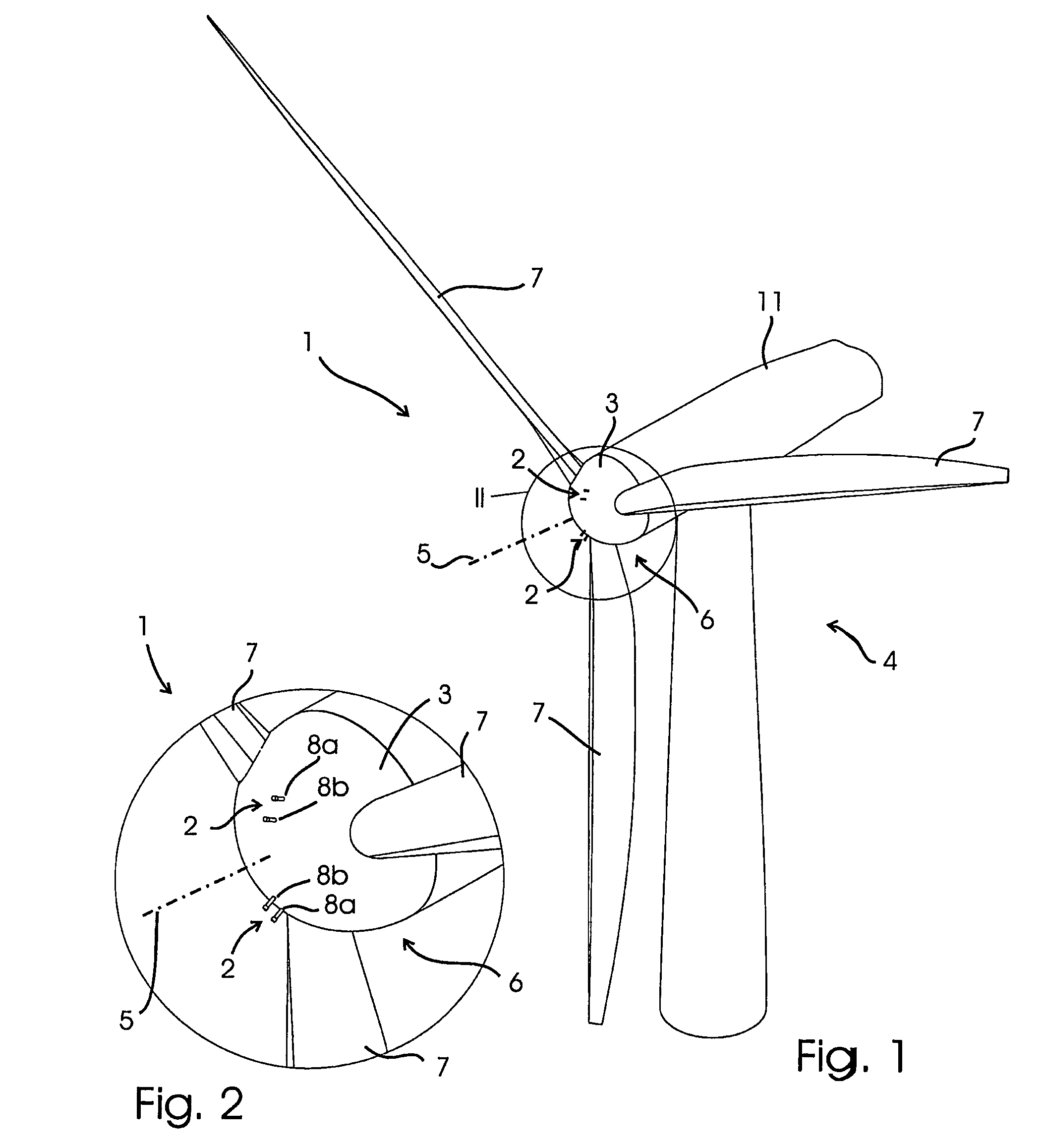
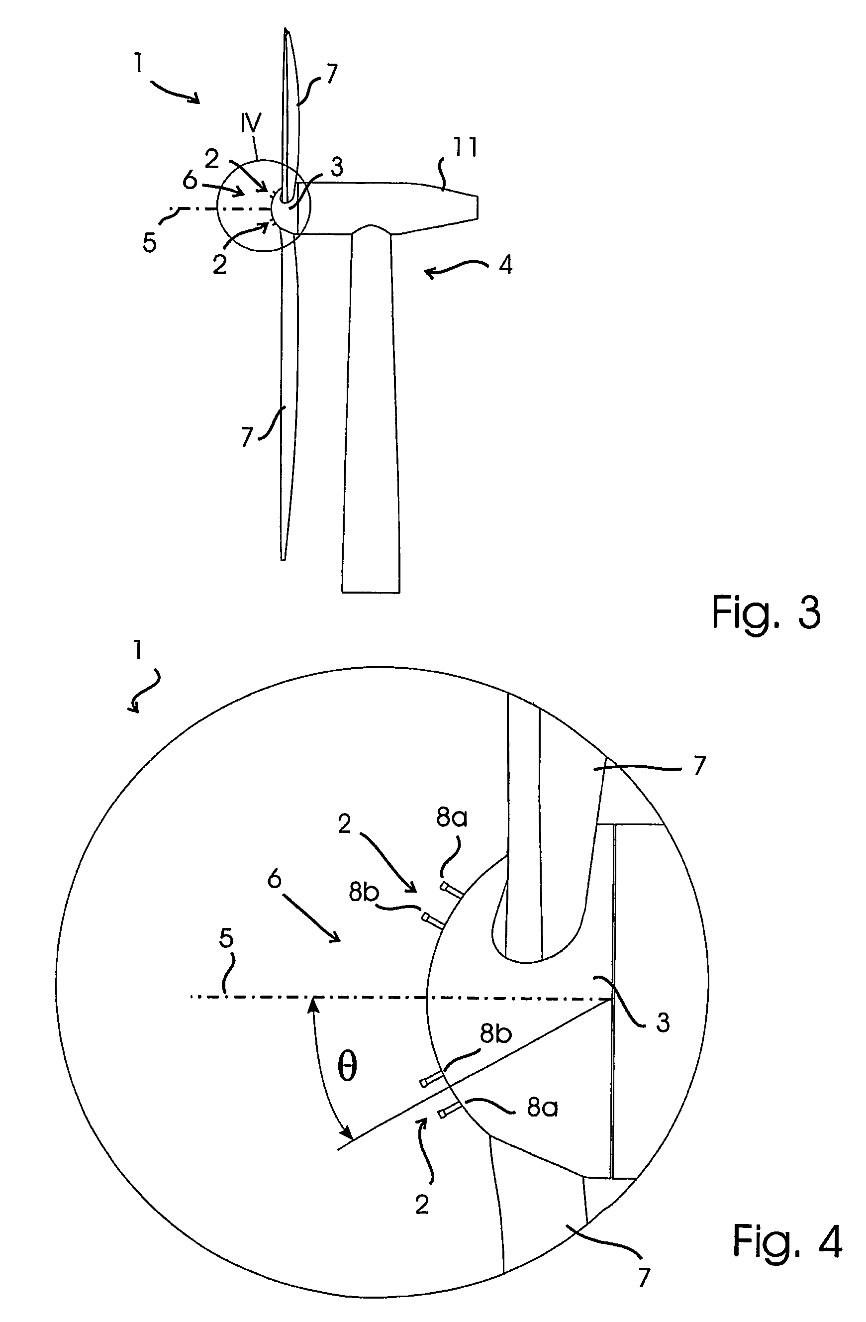
[0054]A first example embodiment 1 of an apparatus according to the invention is shown in FIGS. 1-4. In this example, two one-dimensional (1D) air speed sensors 2 are mounted on the spinner 3 of a wind turbine 4 in a plane which includes the rotation axis 5 of the spinner. As will be known to the person skilled in the art, the rotor 6 is typically comprised of two or more blades 7, which are joined together by the hub. A spinner 3 is attached to the centre of the rotor to streamline the flow around the hub. The hub is located inside the spinner and can therefore not be seen in FIGS. 1-4.

[0055]The front half of the spinner is spherical in order to ensure that the flow around the spinner is well described and smooth. The two 1D sensors 2 measure the component of the air velocity above the boundary layer of the spinner, in the plane in which the sensors lie and in a direction which is tangential to the surface of the spherical spinner at the point where the sensors are mounted.

[0056]In...


PUM


Abstract

An apparatus and a method used to determine the speed and direction of the wind experienced by a wind turbine are provided. The apparatus comprises at least one sensor fixed to the rotor of the wind turbine, an angular sensor to measure the angular position of the rotor of the wind turbine, and a circuit which converts the relationship between the output of the at least one sensor and the output of the angular sensor into the speed and direction of the wind experienced by the wind turbine. According to the invention, the sensing apparatus can measure the wind speed and direction in three dimensions. In addition, mounting the sensors directly to the rotor of the wind turbine results in a very simple and robust installation. Mounting the sensors directly to the rotor also eliminates the turbulence from the rotor and the nacelle of the wind turbine from affecting the sensors.

Description

CROSS REFERENCE TO RELATED APPLICATIONS[0001]This application is a continuation of International application PCT / DK2005 / 000193 filed Mar. 22, 2005, the entire content of which is expressly incorporated herein by reference thereto.FIELD OF INVENTION[0002]The present invention relates to an apparatus and a method used to determine the speed and direction of the wind experienced by a wind turbine.BACKGROUND OF THE INVENTION[0003]The power output of a wind turbine and the loads exerted on the wind turbine by the wind are to a large extent dependent on the orientation of the wind turbine with respect to the wind. Therefore means are available on most wind turbines to adjust the orientation of the wind turbine such that the optimum orientation can be achieved. In addition, means are available on most wind turbines which allow the wind turbine to be adjusted, by for example changing the angle of attack of the blades dependent on the wind speed.[0004]In order for the wind turbine to be opti...

Claims


Application Information

Patent Timeline
Patent Type & Authority Patents(United States)
IPC IPC(8): F03D11/00F03D7/02G01P5/06G01P5/14G01P5/165G01P13/02
CPCF03D7/0204F03D11/0091G01P5/06G01P5/14G01P5/165G01P13/02F05B2270/301F05B2270/32F05B2270/321F05B2270/324F05B2270/802Y02E10/722Y02E10/723F03D17/00Y02E10/72
Inventor PEDERSEN, TROELS FRIIS
Owner ROMO WIND AG
Why Eureka
Try Eureka