
Utilizing track identification fields for timing recovery

a track identification and timing recovery technology, applied in the field of data storage devices, can solve the problems and increasing the length of the pll field in the servo format, so as to achieve the effect of reducing the efficiency of servo forma

Inactive Publication Date: 2008-03-25
SEAGATE TECH LLC
View PDF14 Cites 16 Cited by
  • Summary
  • Abstract
  • Description
  • Claims
  • Application Information

AI Technical Summary

Benefits of technology

"This patent describes an apparatus and method for controlling the position of a recording head when reading data from a data storage medium. The apparatus includes a data storage medium with servo sectors that have a phase locked loop field and a track identification field. A controller is used to control the position of the recording head and a servo demodulator is used to recover timing information from both fields and produce a timing estimate. The technical effect of this invention is to improve the accuracy and efficiency of reading data from the data storage medium."

Problems solved by technology

However, as the storage areal densities increase, the effects of timing errors, channel noise, distortions, and nonlinearities also increase, and the length of the PLL field in the servo format may be too short for an acceptable timing recovery performance.
However the use of a longer PLL field reduces the servo format efficiency.

Method used


Image

  • Utilizing track identification fields for timing recovery
  • Utilizing track identification fields for timing recovery
  • Utilizing track identification fields for timing recovery

Examples


Embodiment Construction

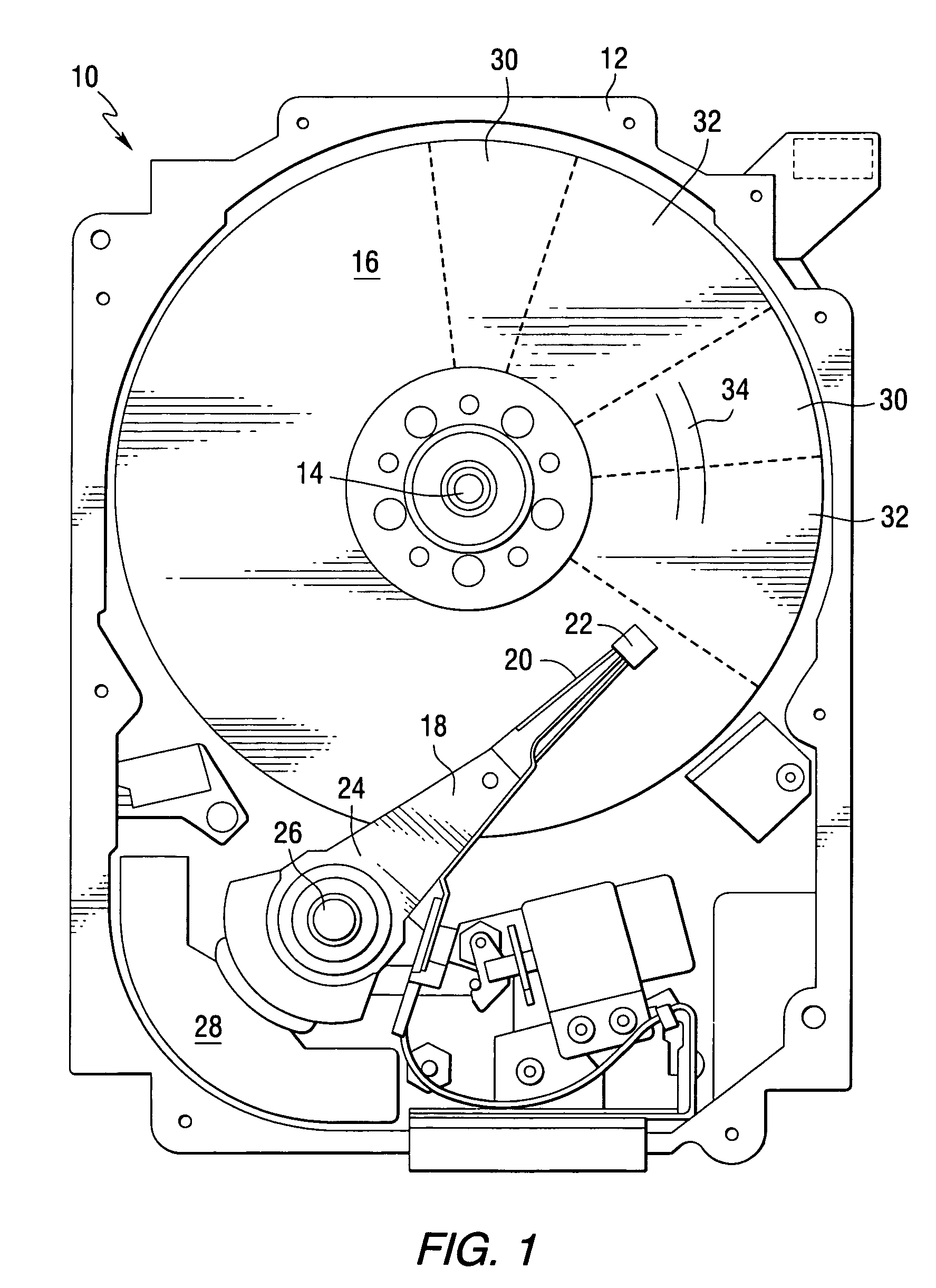
[0030]Referring to the drawings, FIG. 1 is a pictorial representation of the mechanical portion of a disc drive 10 that can be constructed in accordance with the invention. The disc drive includes a housing 12 (with the upper portion removed and the lower portion visible in this view) sized and configured to contain the various components of the disc drive. The disc drive includes a spindle motor 14 for rotating at least one data storage medium 16 within the housing, in this case a magnetic disc. At least one arm 18 is contained within the housing 12, with each arm 18 having a first end 20 with a recording and / or reading head or slider 22, and a second end 24 pivotally mounted on a shaft by a bearing 26. An actuator motor, which may be a voice coil motor 28, is located at the arm's second end 24, for pivoting the arm 18 to position the head 22 to a desired position. The actuator motor 28 is controlled by a controller that is not shown in this view. The disc includes a plurality of s...


PUM

PropertyMeasurementUnit
residual frequencyaaaaaaaaaa
phase offsetaaaaaaaaaa
residual frequency offsetaaaaaaaaaa

Abstract

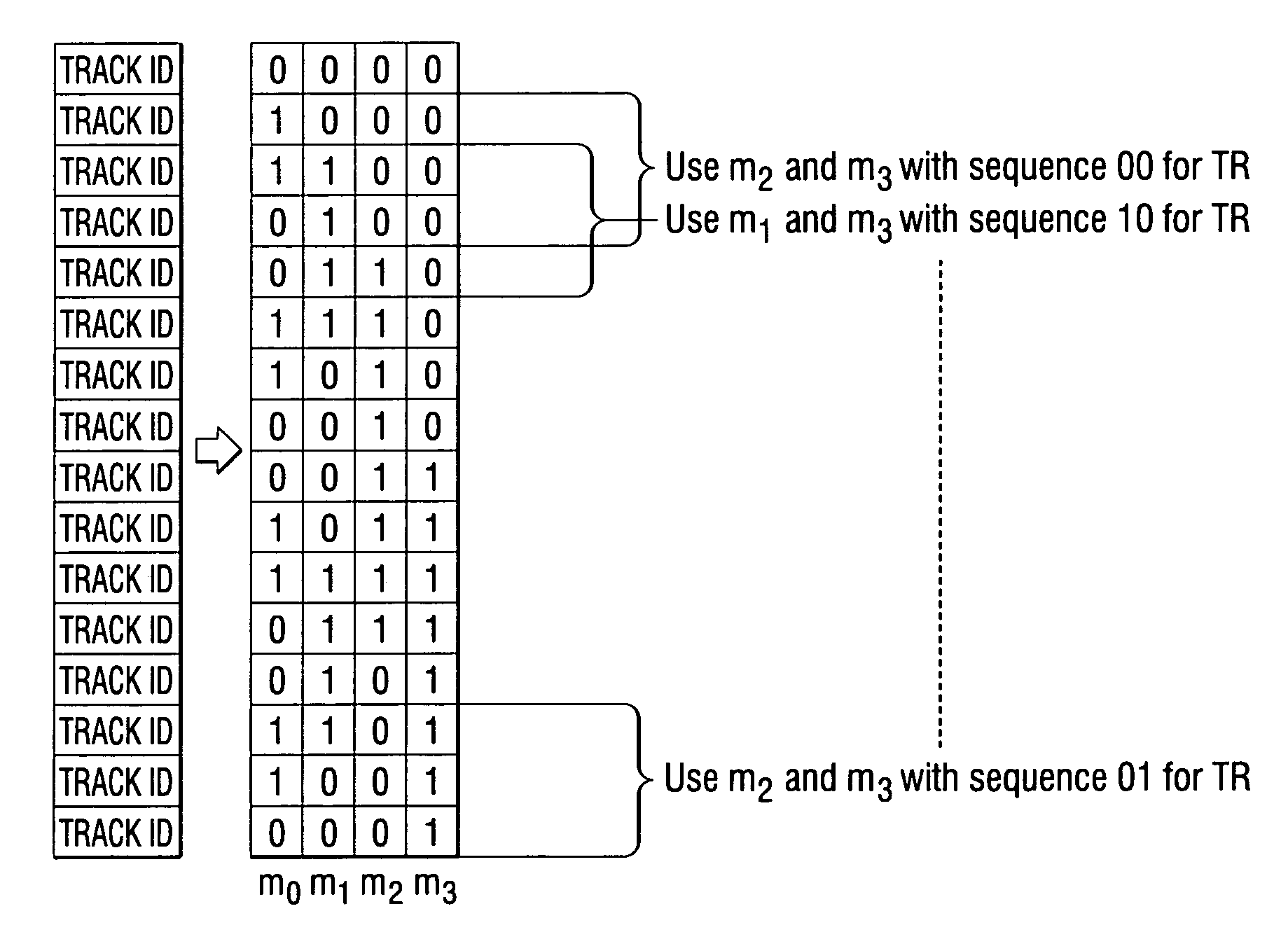
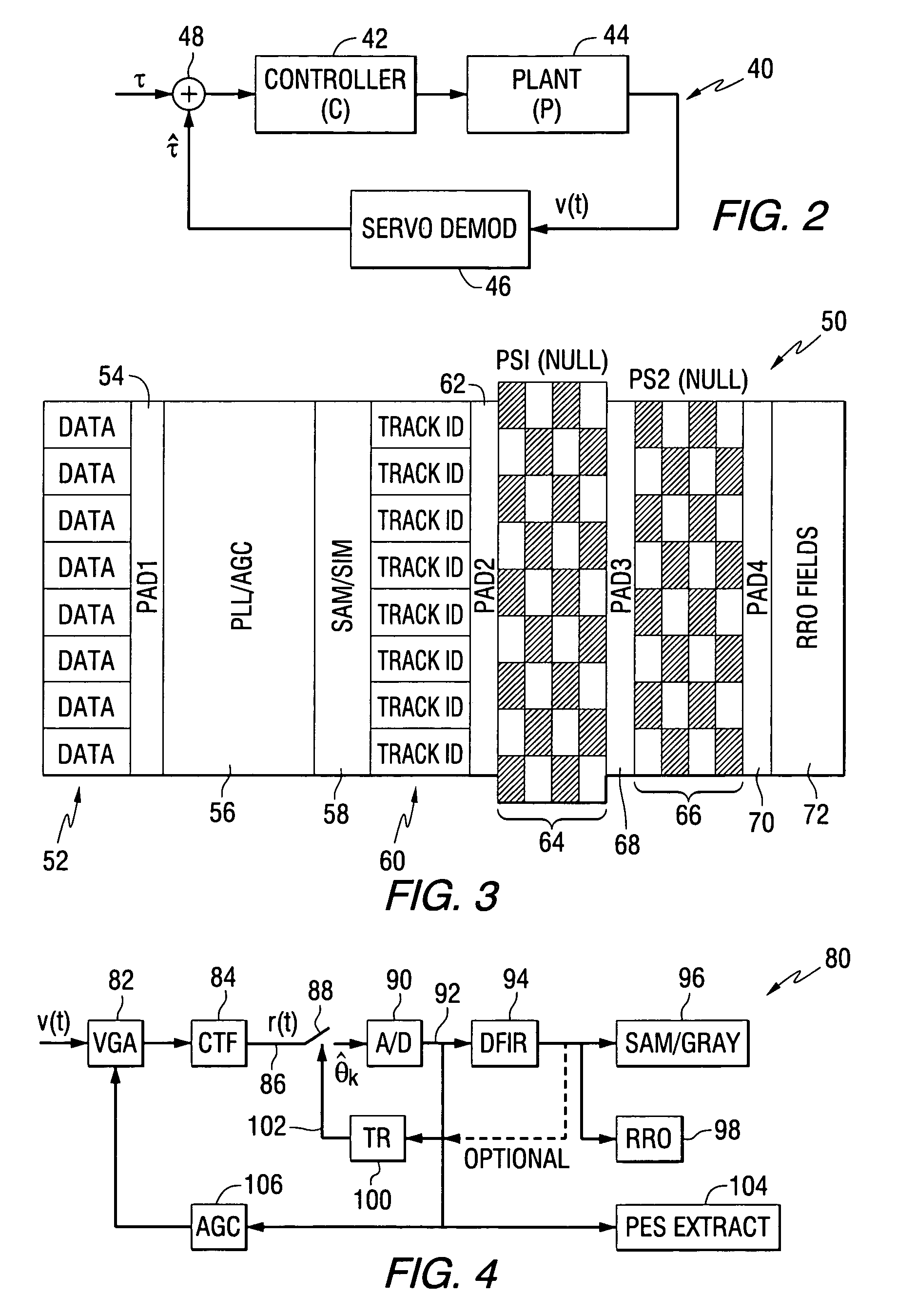
An apparatus comprises a data storage medium having a plurality of servo sectors and a plurality of data sectors, wherein each of the servo sectors includes a phase locked loop field and a track identification field, a controller for controlling the position of a recording head with respect to the data storage medium, and a servo demodulator for recovering timing information from both the phase locked loop field and the track identification field, and for producing a timing estimate. The method performed by the apparatus is also included.

Description

FIELD OF THE INVENTION[0001]This invention relates to data storage devices, and more particularly to methods and apparatus for controlling timing recovery in such devices.BACKGROUND OF THE INVENTION[0002]Disc drives are data storage devices used to store and retrieve digital user data in a fast and efficient manner. A typical disc drive stores such data on one or more magnetic recording discs which are rotated at a constant high speed. An actuator moves one or more data transducing heads to access data stored in tracks defined on the disc surfaces.[0003]With the continued demand for disc drives that provide ever higher data storage capacities and transfer rate performance levels at lower costs, designers continue to provide successive generations of products with ever higher areal data storage densities. It will be recognized that for a given area on the recording surface of a disc, more data can be stored by increasing the number of bits per linear distance along the tracks (e.g., ...

Claims


Application Information

Patent Timeline
Patent Type & Authority Patents(United States)
IPC IPC(8): G11B5/02G11B5/09
CPCG11B5/59688G11B20/1217G11B2020/1287G11B2020/1294G11B2220/2516
Inventor ERDEN, MEHMET FATIHKEIZER, RICHARD LYLEELLIS, TIMOTHY FRANCISSACKS, ALEXEI HIRAM
Owner SEAGATE TECH LLC
Learn More