
Oscillator with digitally variable phase for a phase-locked loop

a phase-locked loop and oscillator technology, applied in the field of phase and frequency control, can solve the problems of phase error, indirect control of phase by controlling frequency not optimal,

Inactive Publication Date: 2003-02-25
GLOBALFOUNDRIES INC
View PDF9 Cites 99 Cited by
  • Summary
  • Abstract
  • Description
  • Claims
  • Application Information

AI Technical Summary

Benefits of technology

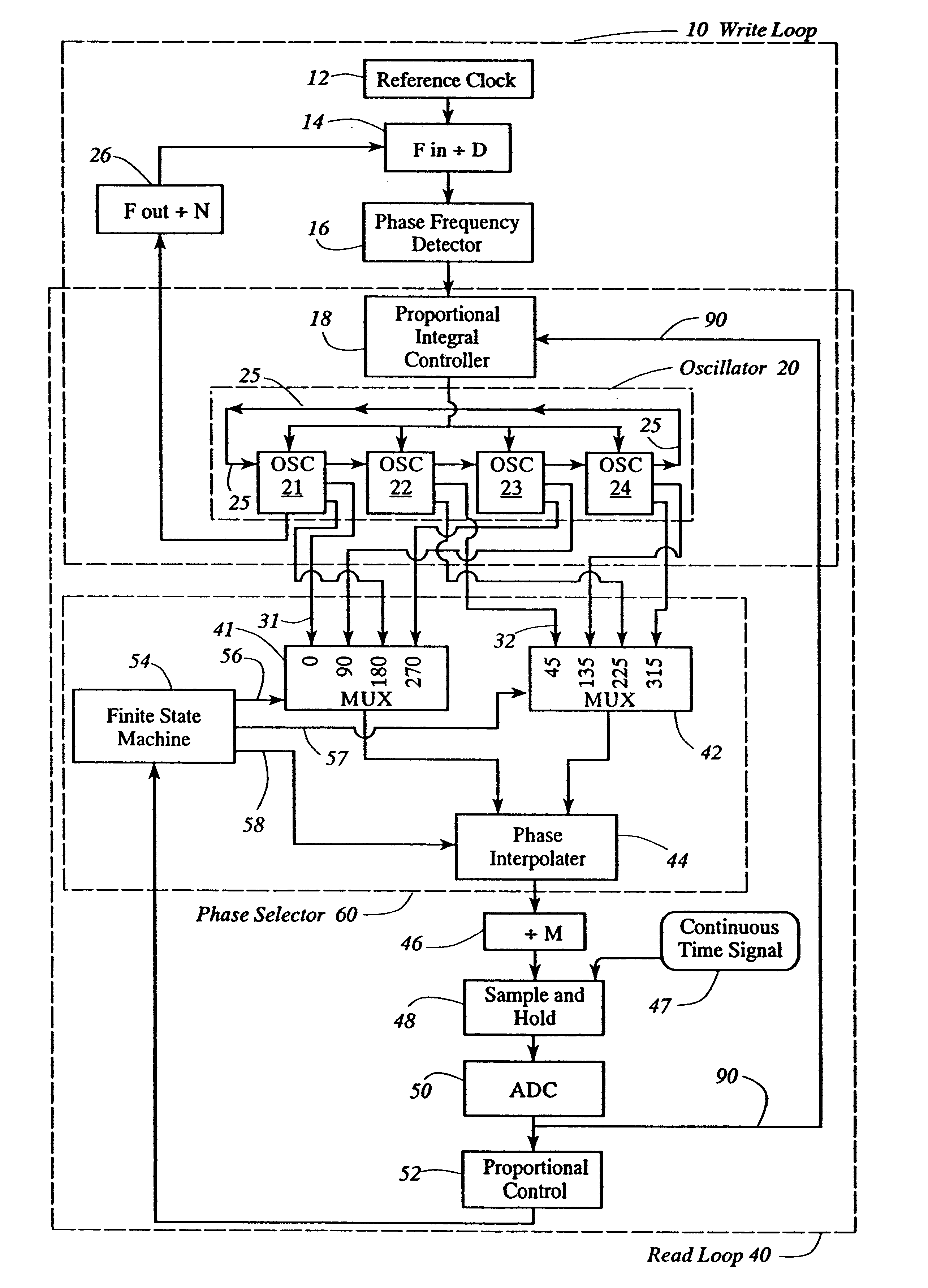
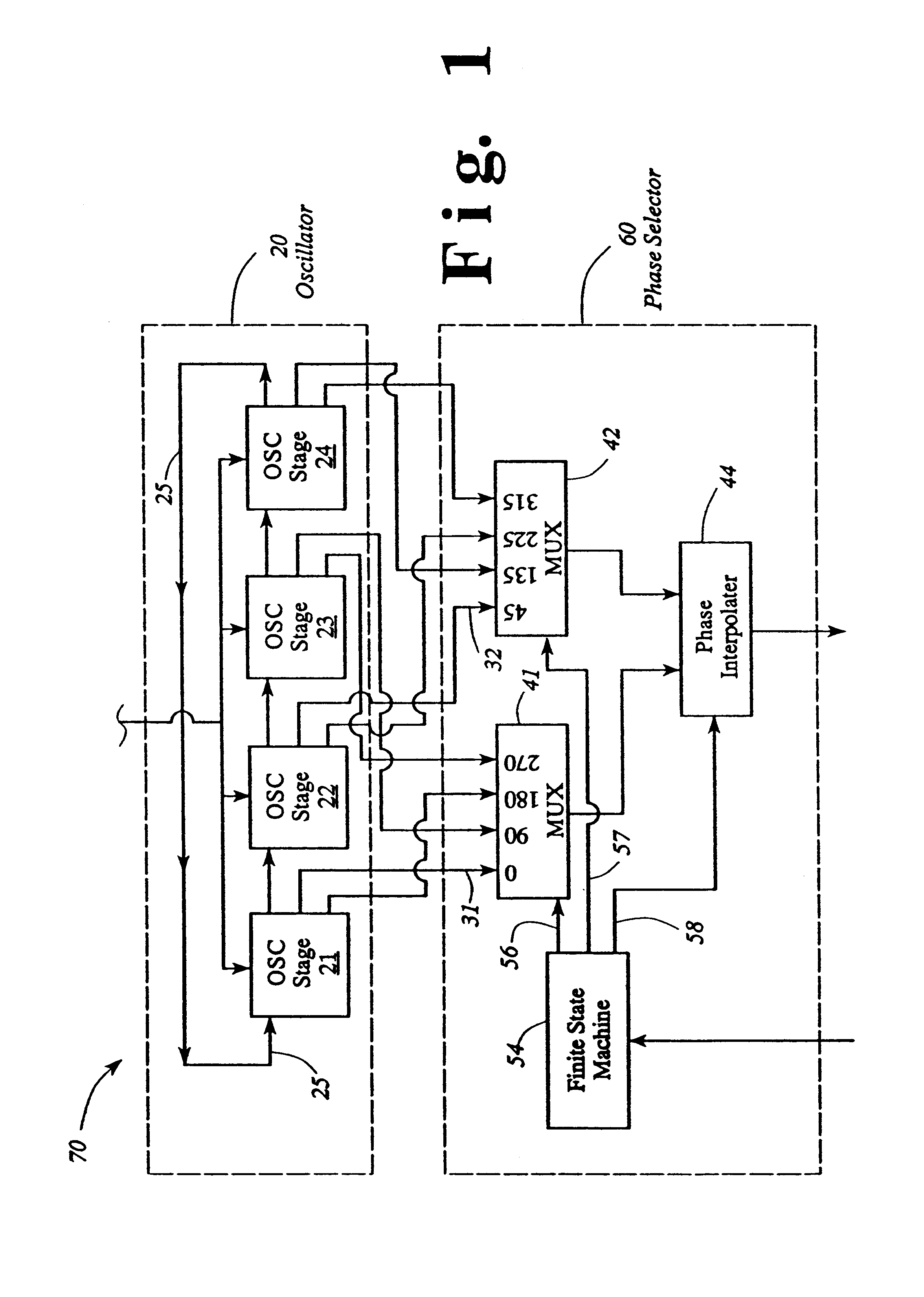
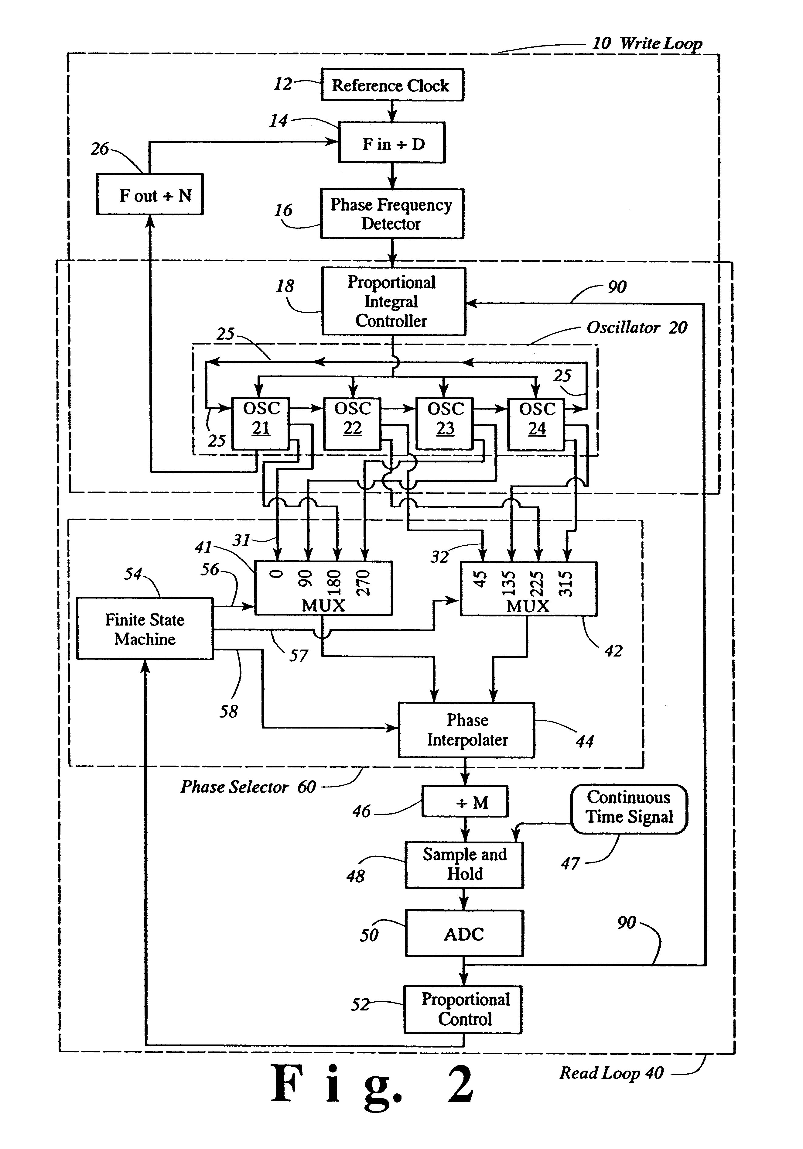
The phase interpolator may comprise first and second current weighted delays which are substantially inversely proportional to a control current wherein the phase interpolator inputs the first phase into the first delay stage while inputting the second phase into the second delay stage. Such first and second delay stages share a total current such that the digital control input causes a fraction F of the current I to flow to the control input of the first delay stage and a fraction (1-F) of the current I to flow to the control input of the second delay stage.
In another aspect, the present invention provides a phase locked loop for controlling a variable phase comprising an oscillator adapted to provide a plurality of phase outputs, a phase selector, a first and second phase outputs selected from the oscillator adapted to provide a plurality of phase outputs, and a phase locked loop. Such phase locked loop comprises the oscillator, phase selector, and first and second phase outputs, wherein the phase selector is adapted to o

Problems solved by technology

Furthermore, in such loop, phase errors are typically measured by a phase-frequency detector (PFD).
However, since integrated circuits typically do not have linear resistive elements adequate for producing resistor elements for filters, a Proportional-Integral-Derivative (PID) Control may alternatively be used to control phase.
However, in a digitally controlled phase locked loop, the gain of the closed loop varies with operating frequency, and thus controlling phase indirectly by controlling the frequency is not optimum.

Method used


Image

  • Oscillator with digitally variable phase for a phase-locked loop
  • Oscillator with digitally variable phase for a phase-locked loop
  • Oscillator with digitally variable phase for a phase-locked loop

Examples


Embodiment Construction

)

In describing the preferred embodiment of the present invention, reference will be made herein to FIGS. 1-3 of the drawings in which like numerals refer to like features of the invention. Features of the invention are not necessarily shown to scale in the drawings.

The present invention provides an improved method and apparatus for independently controlling phase and frequency using an oscillator in combination with a phase selector within a digitally controlled phase-locked loop. The combined oscillator with the phase selector provides a digitally controlled variable phase of a read timing loop within a read phase locked loop in read channel integrated circuits associated with data storage devices. In a preferred embodiment, the present invention provides two separate controls, particularly a first control for phase and a second control for frequency. The phase and frequency are controlled independently of each other, wherein the first control, controlling phase, is applied to a ph...


PUM


Abstract

The present invention provides an improved method and apparatus for independently controlling phase and frequency using an oscillator having a plurality of stages in combination with a phase selector within a digitally controlled phase-locked loop, preferably, a read phase locked loop. The present invention provides a digitally controlled variable phase of the read timing loop in read channel integrated circuits associated with data storage devices. The phase selector has a digitally controlled fine interpolator with 12 states for further fine interpolation between at least two multiplexer phase outputs to provide a single phase output selected from a range comprising at least 2pi in selectable variable phase increments of 2pi / 96 radian. The combined oscillator with the phase selector within a phase locked loop controls phase by exact fractional increments of equally space phases of the operating frequency within the phase locked loop, therein controlling phase at all operating frequencies.

Description

1. Field of the InventionThe present invention relates generally to phase and frequency control. More particularly, it relates to a method and apparatus for controlling phase and frequency using an oscillator in combination with a phase selector within a digitally controlled phase-locked loop.2. Description of Related ArtTypically, read channel integrated circuits associated with data storage devices, such as magnetic hard disk drives, have two modes of operation for controlling the system clock: a write mode having a write loop and a read mode having a read loop. In the write loop, the system clock is synthesized from an external reference clock, such as the output of a crystal oscillator. The synthesized frequency is typically a rational multiple, N / D (where N and D are integers), of the reference clock. Frequency synthesis is a well known technique in the art. In the write loop of the timing control loop, specified data is obtained and written to a magnetic medium at this synthes...

Claims


Application Information

Patent Timeline
IPC IPC(8): G11B20/14G11B21/18G11B21/16G11B5/55H03L7/087H03L7/099H03L7/08H03L7/16H03L7/18H03L7/091
CPCG11B5/5569G11B20/1025G11B20/1403G11B21/18H03L7/18H03L7/0996H03L7/0998H03L7/087H03L7/091
Inventor MASENAS, CHARLES J.SEMAN, TROY A.
Owner GLOBALFOUNDRIES INC
Learn More