Permanent magnet synchronous motor and controller therefor

a permanent magnet synchronous and controller technology, applied in the direction of motor/generator/converter stopper, electronic commutator, dynamo-electric converter control, etc., can solve the problems of high-resolution position sensor fragileness, high-performance mcu is required for sensorless methods, and the need for high-performance mcu is often high-cost, the effect of greatly simplifying the control circuit of 3-phase sinusoidal pwm

Inactive Publication Date: 2005-11-10
AISIN SEIKI KK
View PDF6 Cites 100 Cited by
  • Summary
  • Abstract
  • Description
  • Claims
  • Application Information

AI Technical Summary

Benefits of technology

[0022] The function of the Clark Transformation in Equation (3) can be implemented by either hardware or software without difficulty. The amplitude of the 3-phase sinusoidal signals will be unity because they have been normalised. They are the inputs fed into PWM choppers. In the conventional PWM control, the amplitude of the high-frequency triangle carrier of PWM is fixed, and controlling the average output of PWM is accomplished by adj...

Problems solved by technology

However, high-resolution position sensors are usually fragile, unreliable and expensive.
Unfortunately accurate position determination is extremely difficult at start-up and very low speed due to the lack of position-dependent signals.
Also, a high-performance MCU is required for sensorless methods due to the implementation of complex algorithms as well.
However, due...

Method used


Image

  • Permanent magnet synchronous motor and controller therefor
  • Permanent magnet synchronous motor and controller therefor
  • Permanent magnet synchronous motor and controller therefor

Examples


Embodiment Construction

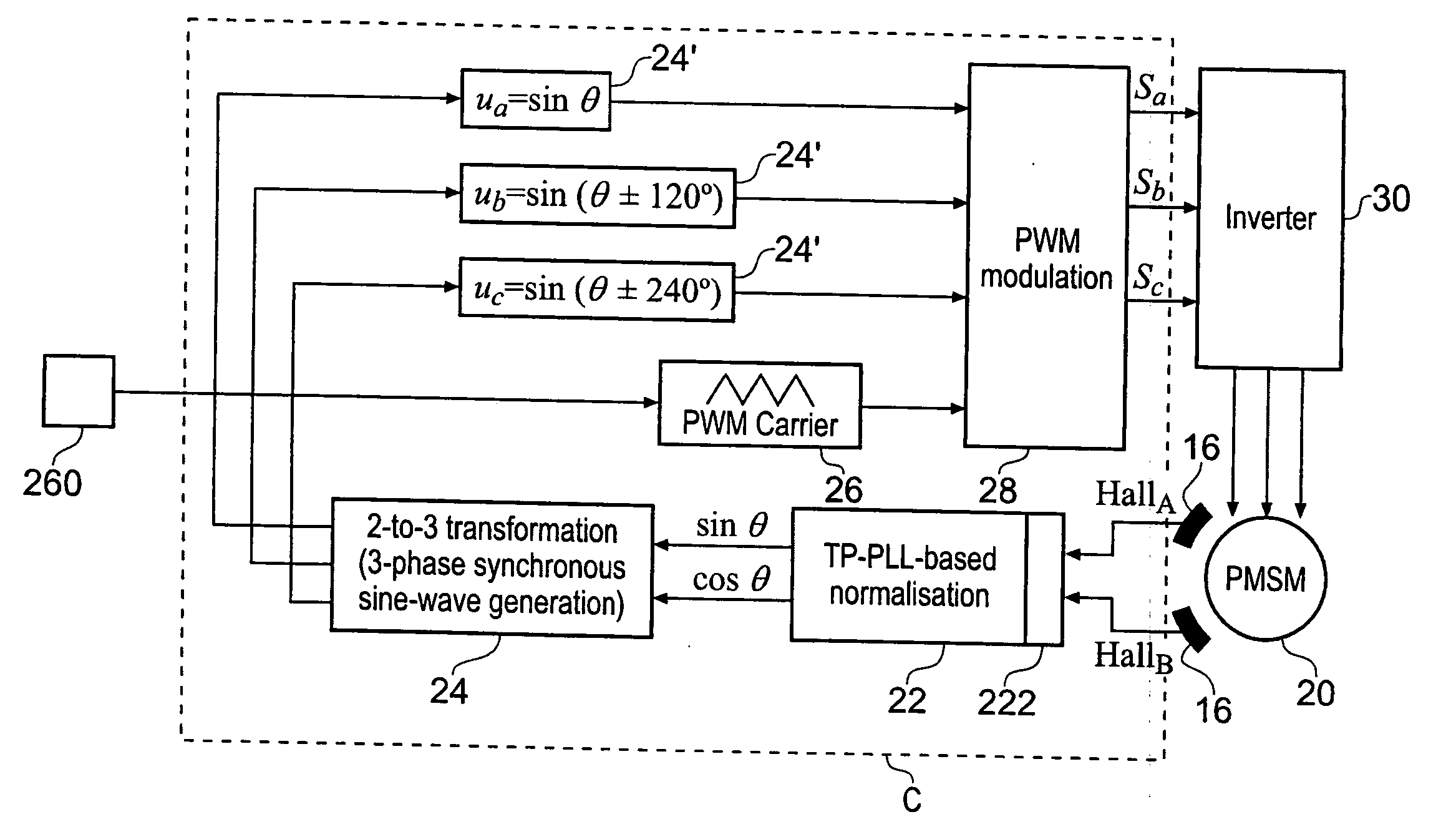
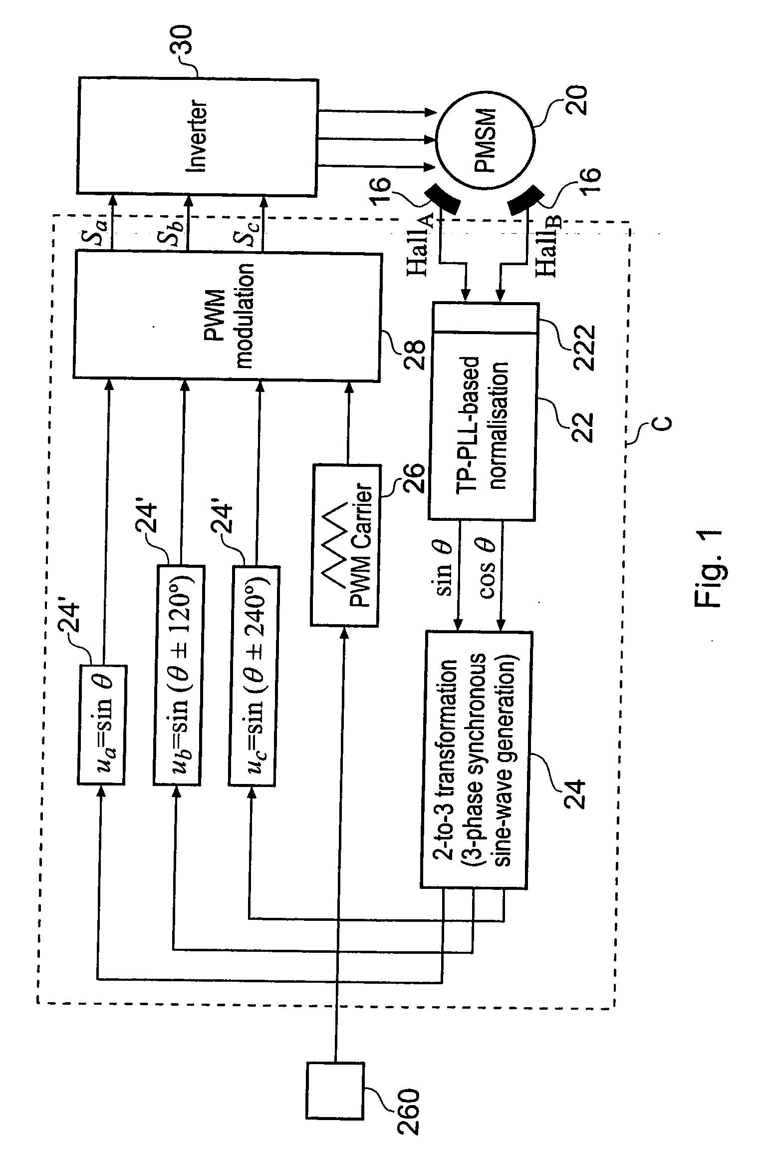
[0043]FIG. 1 is a schematic diagram of an open-loop sine-wave drive according to an embodiment of the invention, comprising a PMSM 20 and an open loop controller. The controller comprises two Hall effect sensors 16 (HallA and HallB) which have a linear response to sensed magnetic field strength. In this example the sensors 16 are spaced by 90 electrical degrees but may be at any other angle except 180n where n is an integer: n may be 0, 1, 2, etc.. A Two Phase Phase Locked Loop TP-PLL 22 normalises the outputs of the two Hall sensors 16 and provides normalised outputs sinθ and cosθ. A 2-to-3 Clark transformation function block 24 converts the two phases sinθ and cosθ, to three phases ua, ub and uc as indicated at 24′. A PWM chopper 28 modulates a triangular carrier produced by a carrier source 26 to output pulse width modulated phases Sa, Sb and Sc. An inverter 30 converts the PWM phases Sa, Sb and Sc to sinusoidal currents which energise the 3 phase stator of the PMSM 20. In accord...


PUM


Abstract

A low-cost sine-wave drive for a 3-phase permanent magnet synchronous AC machines (PMSM) in open-loop control is based on the measurements of two linear Hall sensors. The two Hall sensors are excited by a magnetic ring with the same pole number as the PMSM rotor magnet and sinusoidal flux distributions. The output signals of the Hall sensors are unified through a two-phase-type phase-lock-loop in order to reduce the impact of the sensor mounting non-uniformity during mass production. The peak torque and speed of motor is simply controlled by adjusting the amplitude of pulse-width-modulation carrier. Smooth torque control is achieved due to sinusoidal 3-phase currents. Such a simple sine-wave drive can be achieved with or without the assistance of a micro-controller unit (MCU). No current sensor is required for the motor phase current detection. This motor can be used in industrial applications where there is no strict requirement on torque response and constant speed control of PMSM machines.

Description

CROSS REFERENCE TO RELATED APPLICATIONS [0001] This application is based on and-claims priority under 35 U.S.C. §119 with respect to Great Britain Patent Application 9410037.6, filed on May 5,2004, the entire content of which is incorporated herein by reference FIELD OF THE INVENTION [0002] The present invention relates to a permanent magnet synchronous motor having a controller. The present invention also relates to a controller for such a motor. BACKGROUND [0003] The sinusoidal control of AC machines is commonly achieved by using the well-known vector control (also called field-orientated control) theory. It has been widely used for variable speed control of 3-phase asynchronous induction motors and synchronous PM AC machines. It delivers sinusoidal control of 3-phase current of AC motors with low torque ripple. Due to the involvement of extensive computation, a high-speed micro-controller, DSP or microprocessor (MCU) is usually required. Accurate rotor position information is ess...

Claims


Application Information

Patent Timeline
IPC IPC(8): H02K29/08H02P6/06H02P6/16H02P6/10H02P25/02
CPCH02P25/023H02P6/16H02P25/03H02K29/08
Inventor CHEN, XIAOJIANGPRIDE, ADAMIWASAKI, SHINICHIRO
Owner AISIN SEIKI KK
Why Eureka
Try Eureka