Method and system for transport protocol reconstruction and timer synchronization for non-intrusive capturing and analysis of packets on a high-speed distributed network

a high-speed distributed network and packet-reconstruction technology, applied in data switching networks, frequency-division multiplexes, instruments, etc., can solve the problem that the buffering effect cannot be eliminated completely, and still does not eliminate the packet-reordering problem altogether, so as to achieve less likelihood and higher efficiency

Inactive Publication Date: 2008-03-25
NARUS
View PDF14 Cites 27 Cited by
  • Summary
  • Abstract
  • Description
  • Claims
  • Application Information

AI Technical Summary

Benefits of technology

[0023]The present invention provides a method for reconstructing transport protocol data flow from a sequence of captured data packets in a more efficient manner by delaying a determination that a missing packet was lost for a certain period of time measured by a timer(s). The data packets may be TCP, WAP, SCTP, or other packets. The data packets are transmitted from a first device to a second device in a first direction on a first channel and from the second device to the first device in a second direction on a second channel. A first part of the data packets are captured by a first packet capturing device on the first channel and time stamped by a first timer, and a second part of the data packets are captured by a second packet capturing device on the second channel and time stamped by a second timer.
[0026]The method for reconstructing data flow according to the present invention operates in real time as the data packets are captured. As a result, the method provides a real-time response and minimized amount of memory required for data packet reconstruction.
[0030]The data packet reordering method and system of the present invention delays a determination that missing packets in a data packet stream are lost, by deferring such determination until the acknowledgement timers and the retransmission timers expire at which point such a determination can be more reliably made. As such, the method and system of the present invention has less likelihood of determining that missing packets are lost even though they were in fact received at a later time, if they are received prior to expiration of the acknowledgement and retransmission timers. Thus, the data packet reordering method and system will encounter fewer instances of lost packets, resulting in higher efficiency in reconstructing data packets communicated between network applications.

Problems solved by technology

However, none of these conventional packet analysis applications are effective in TCP reconstruction for non-intrusive capturing and analysis of packets on a high speed distributed network, such as a full-duplex 100 Mbps network, Gigabit network, or POS network using separate physical channels for transmitting in opposite directions, especially when the packets are captured at different geographical locations of a distributed network.
This could be improved by using specialized NICs that employ an inter-NIC timer, however the “buffering” effect cannot be eliminated completely due to necessity of inter-NIC buffering and link delays.
Moreover, this approach still does not eliminate the packet-reordering problem altogether.
Further, in a distributed configuration such as that shown in FIG. 4, the packet re-ordering problem becomes more serious than that of the packet capturing system 300 in FIG. 3.
Considering that modern high-speed optical links can carry millions of packets per second, the out-of-order packet capturing problem becomes a major roadblock for packet analysis in distributed networks.
However these techniques are associated with substantial additional cost and specialized equipment, and still cannot completely eliminate the timer mis-synchronization problem.
Such requirements make these techniques unacceptable for many deployments and network configurations.
In addition, unpredictable delays associated with buffering and interrupt latency cause time-stamping mistakes, even when precisions GPS timers are utilized.
Since the client side 502 packets are time-stamped with a time later than the server side 504 packets, it causes a packet reordering problem.
This is because conventional transaction reconstruction methods consider packets in the order in which they are time-stamped and assume that missing packets in the time-stamped sequence of packets were lost during the packet capturing process.
In other words, conventional transaction reconstruction methods are not capable of deferring the decision that a packet was lost.

Method used


Image

  • Method and system for transport protocol reconstruction and timer synchronization for non-intrusive capturing and analysis of packets on a high-speed distributed network
  • Method and system for transport protocol reconstruction and timer synchronization for non-intrusive capturing and analysis of packets on a high-speed distributed network
  • Method and system for transport protocol reconstruction and timer synchronization for non-intrusive capturing and analysis of packets on a high-speed distributed network

Examples


Embodiment Construction

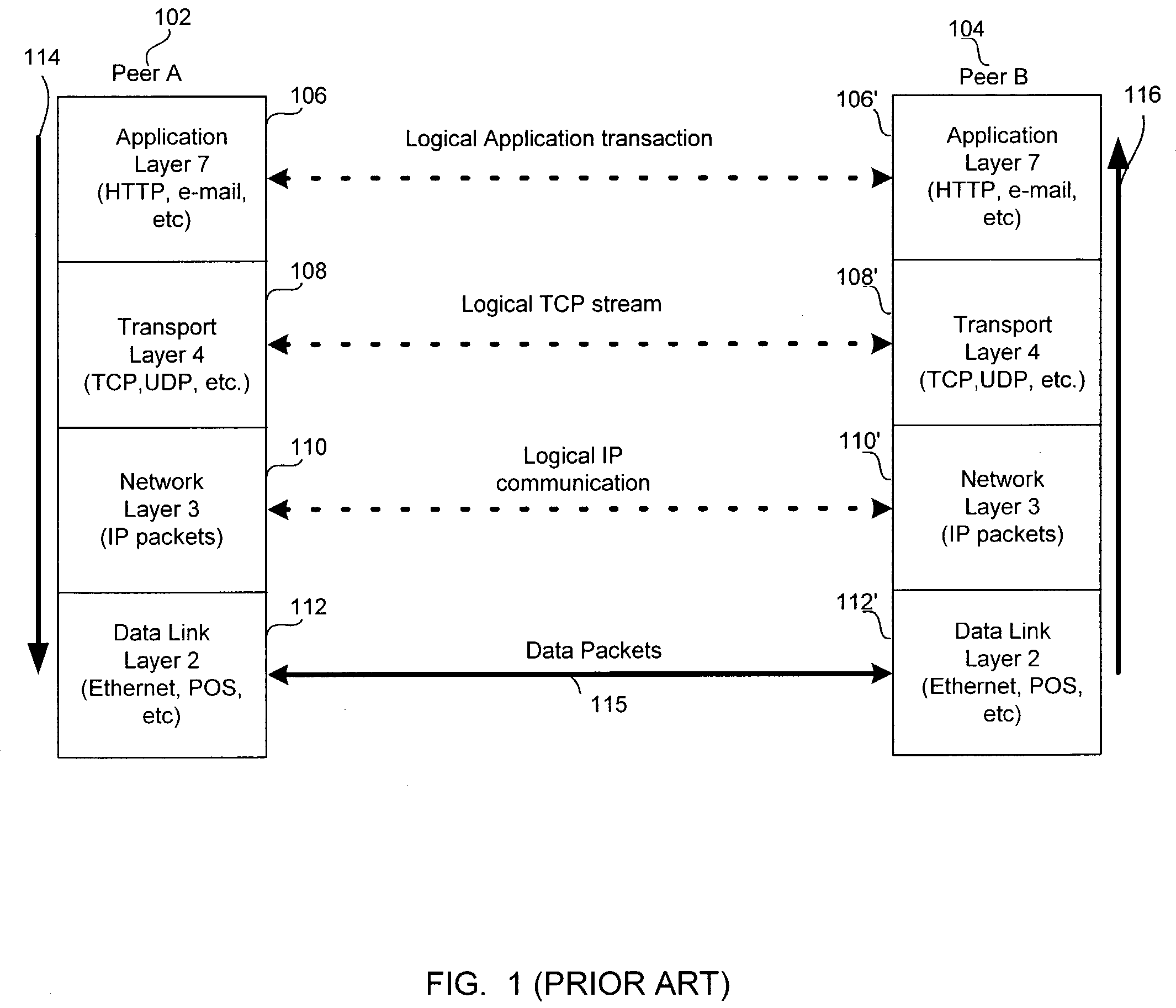
[0046]The embodiments of the present invention will be described below with reference to the accompanying drawings. Where possible, like reference numerals are used for like elements in the accompanying drawings. For convenience of explanation, the following description is directed to TCP (Transport Control Protocol) as a specific implementation of the general reliable transport protocol (layer 4 protocol). However, one skilled in the art would recognize that the present invention is compatible other reliable transport protocol implementations, such as a WAP (Wireless Access Protocol), SCTP (Stream Control Transmission Protocol), and the like.

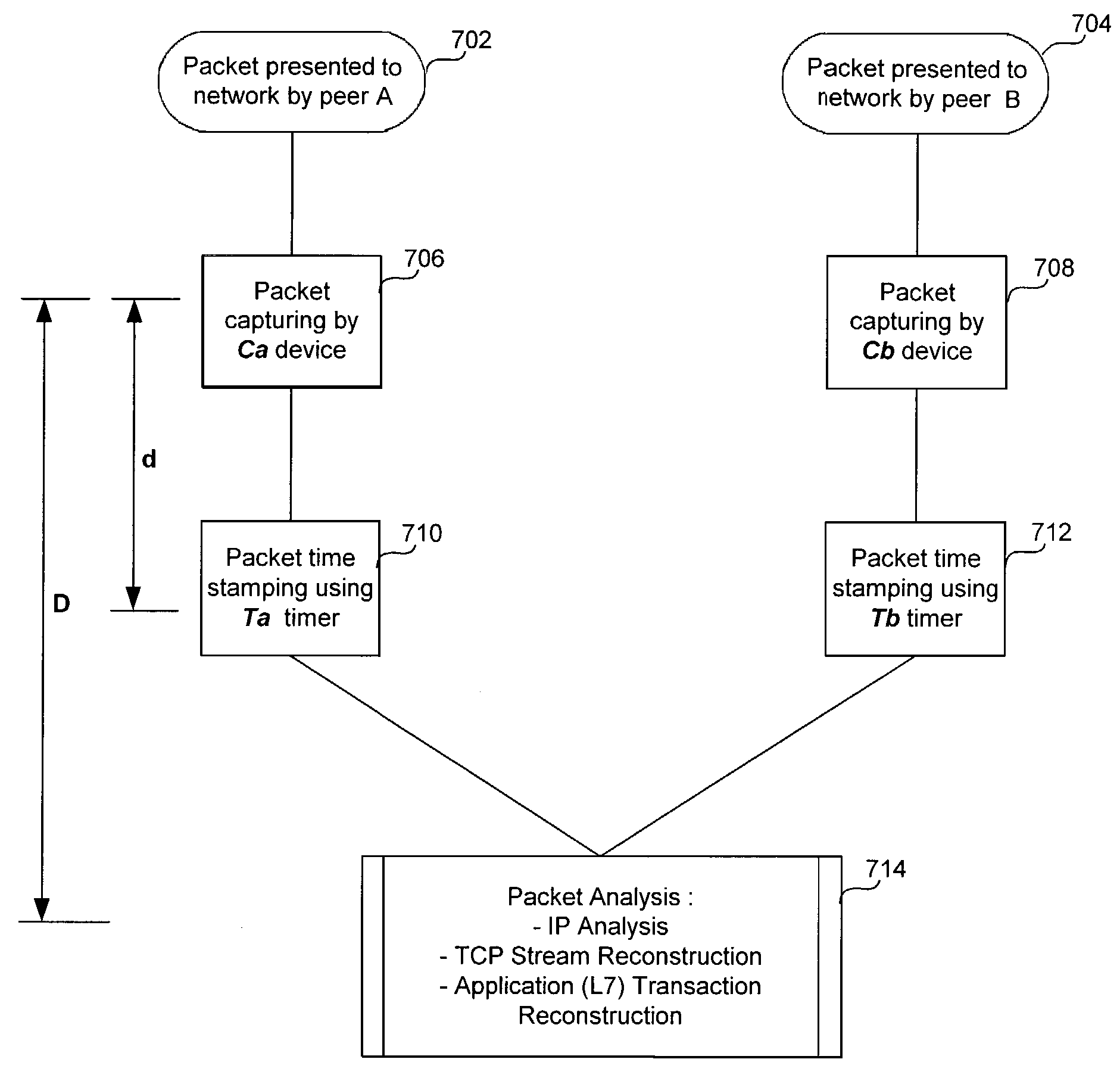
[0047]FIG. 7A is a functional flow diagram illustrating the packet capturing and analysis system according to one embodiment of the present invention. For the purpose of explaining the operation of the packet capturing and analysis system of the present invention, it is assumed that two Internet Protocol (IP) peers A and B (not shown) are conne...


PUM


Abstract

A transport protocol data flow reconstruction method delays determination that a missing packet is lost for a period of time. For an evaluated TCP packet in a first direction, the method determines if a TCP packet is missing in a second direction, in which case the method stores the evaluated TCP packet in a list and creates an acknowledgement timer indicating a maximum time to wait until treating the missing TCP packet as lost. Expiration of the acknowledgment timer indicates a missing packet in the second direction. The method determines if a TCP packet is missing in the first direction, in which case the method stores the evaluated TCP packet in the list and creates a retransmission timer indicating a maximum time to wait until treating the missing TCP packet as lost. Expiration of the retransmission timer indicates a missing packet in the first direction.

Description

TECHNICAL FIELD[0001]The present invention relates generally to transport protocol reconstruction, and more specifically, to a method for Transmission Control Protocol (TCP) reconstruction and timer synchronization for non-intrusive capturing and analysis of packets on a high-speed distributed network.BACKGROUND OF THE INVENTION[0002]With the advent of the Internet, modern computer applications not only operate on isolated systems but also communicate with each other on data communication networks. These network applications communicate with each other by sending and receiving packets to and from each other on the networks. Network applications capture, process and analyze the packets on the network in order to communication with each other.[0003]Figure (“FIG.”) 1 is a diagram illustrating conventional communication between two network applications using the logical layers of a typical Transmission Control Protocol / Internet Protocol (TCP / IP) application. As shown in FIG. 1, two netw...

Claims


Application Information

Patent Timeline
Patent Type & Authority Patents(United States)
IPC IPC(8): H04L12/56H04L12/26H04L29/06H04L29/08
CPCH04L29/06H04L43/18H04L47/193H04L69/163H04L69/16H04L69/326H04L43/00H04L9/40
Inventor KHIRMAN, STANISLAV
Owner NARUS
Why Eureka
Try Eureka