Techniques for debugging computer programs involving multiple computing machines

a technology for debugging computer programs and computing machines, applied in computing, error detection/correction, instruments, etc., can solve problems such as manual process tediousness, human error risk, and failure to perform correctly when executed by virtual machines

Inactive Publication Date: 2008-03-25
ORACLE INT CORP
View PDF14 Cites 94 Cited by
  • Summary
  • Abstract
  • Description
  • Claims
  • Application Information

AI Technical Summary

Benefits of technology

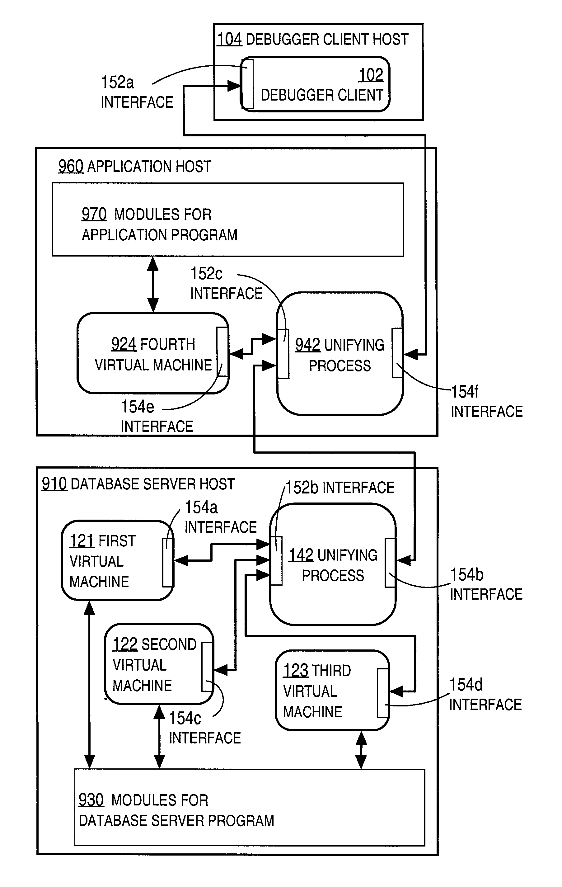
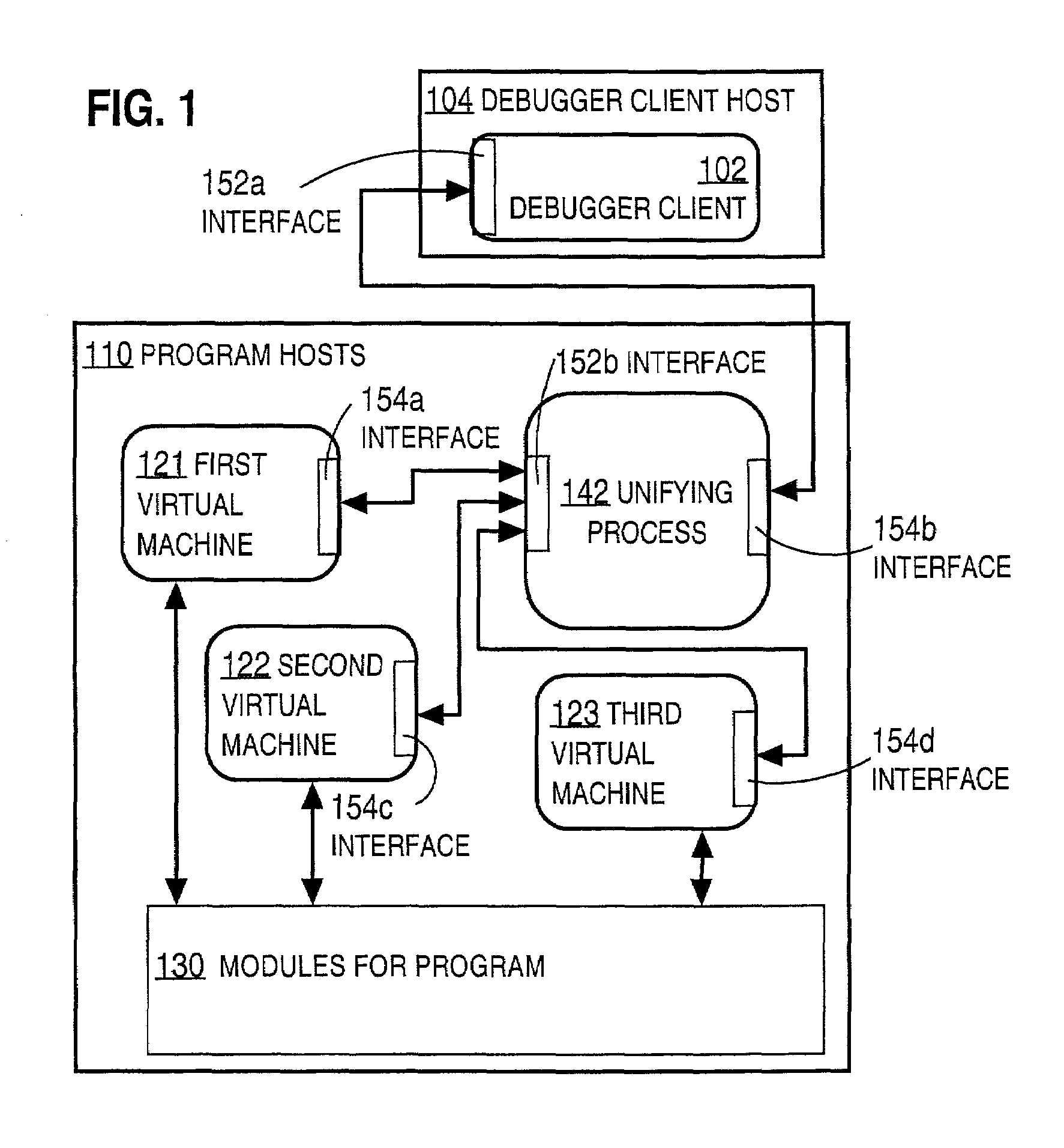
[0020]The unifying component thus allows a single, conventional debugger client to control the debugging operations of several machines.

Problems solved by technology

When a program is written or modified, it may be compiled successfully into coded instructions, and yet still not perform correctly when executed by the virtual machine.
However, while running, the accounting program may cause a database procedure, such as an average salary computation procedure, to be launched by a database server and run on a second processor on a different device on the network.
While computer programs now often include multiple modules executed by different virtual machines or different instances of the same virtual machine, the debuggers currently available are typically not designed to handle these situations.
The manual process is tedious and subject to increased risk of human errors.

Method used


Image

  • Techniques for debugging computer programs involving multiple computing machines
  • Techniques for debugging computer programs involving multiple computing machines
  • Techniques for debugging computer programs involving multiple computing machines

Examples


embodiment 620

[0095]FIG. 6B is a flowchart illustrating an embodiment 620 of a method at a unifying process for debugging a computer program executed by multiple virtual machines based on a message from a debugger client.

[0096]In step 623, a debugging message is received at the unifying process from a debugger client. The message includes one or more operations, breakpoints or variable objects. The breakpoints are indicated by module identifiers and position indicators, such as module names and statement line numbers. It is assumed, for purposes of illustration, that module 440 is named “AtoQS” and that statement 444 occurs at a line number having a value “444.” For example, to set a breakpoint at statement 444 of JAVA module 440 in FIG. 4, the debug message includes data indicating “set breakpoint” and “AtoQS” and “line=444.” If the method is used recursively, a sequence number can be added to the module identifier. In some embodiments (such as embodiment using JDBWP to pass request information ...

embodiment 640

[0109]FIG. 6C and FIG. 6D make up a flowchart illustrating an embodiment 640 of a method at a unifying process for debugging a computer program executed by multiple virtual machines based on debugging information received from a virtual machine.

[0110]In step 641, a message is received from a virtual machine of the plurality of virtual machines with debugging information. The virtual machine that sends the message is a current virtual machine. The other instantiated virtual machines are waiting for the current virtual machine to finish processing and return control to one of the other virtual machines. The message may indicate the current virtual machine is completing execution of a routine, that the current virtual machine is beginning execution of a routine, that the current virtual machine has reached a breakpoint, or that the contents of one or more variable objects are being returned. In some embodiments, the data are expressed in the language constructs of a different language ...


PUM


Abstract

Techniques for debugging a computer program that includes multiple modules executing on multiple machines include receiving, at a unifying component, first data from a first machine. The first data indicates debugging information generated by the first machine. Second data is also received at the unifying component from a second machine. The second data indicates debugging information generated by the second machine. Based on the first data and the second data, third data is formed indicating a single integrated representation of debugging information for the computer program. The unifying component allows debugging information from several machines to be integrated and then presented to a user through a single debugger client.

Description

CROSS REFERENCE TO RELATED APPLICATION[0001]This application claims benefit of Provisional Application 60 / 324,722, filed Sep. 24, 2001, the entire contents of which is hereby incorporated by reference as if fully set forth herein, under 35 U.S.C. §119(e).FIELD OF THE INVENTION[0002]The present invention relates to debugging a computer program. In particular, the present invention relates to debugging a computer program that is executed by multiple virtual machines.BACKGROUND OF THE INVENTION[0003]Computer programs are instructions for controlling processors in computing devices. Computer programs are typically written in one or more high level languages that are easy for a human being to understand. These source language statements are then typically compiled by a special type of program called a compiler and converted to coded instructions, which often correspond to the actual operations performed by a processor in a computer device. Frequently the coded instructions are not identi...

Claims


Application Information

Patent Timeline
Patent Type & Authority Patents(United States)
IPC IPC(8): G06F9/44G06F9/45
CPCG06F11/362
Inventor ALPERN, DAVID M.
Owner ORACLE INT CORP
Why Eureka
Try Eureka