Calibration gauge for hair cutter bladesets

a bladeset and calibration gauge technology, applied in the direction of drilling/boring measurement devices, manufacturing tools, instruments, etc., can solve the problems of end users, difficult to accurately adjust the bladeset spacing, and difficulty in recalibration, so as to achieve more accurate cutting, small gap, and more precision

Active Publication Date: 2008-04-01
WAHL CLIPPER
View PDF22 Cites 23 Cited by
  • Summary
  • Abstract
  • Description
  • Claims
  • Application Information

AI Technical Summary

Benefits of technology

[0006]The above-listed objects are met or exceeded by the present blade calibration gauge that enables consistent, desired adjustment of the distance between the toothed ends of the blades in the bladeset to an extremely small distance. This provides the user with the ability to reliably obtain a smaller, more precise gap between the blade edges than previously possible. The result is more accurate cutting by a hair cutter without causing damage to the subject's skin.

Problems solved by technology

Currently, such adjustments are performed by the naked eye, with the user (typically a hair professional) making difficult, precise adjustments to obtain the desired small gap between the toothed blade edges.
Through normal use and maintenance, end users often are faced with the task of recalibrating the bladeset spacing.
However, the end users were forced to perform such recalibration by eye.
This method has obvious drawbacks due to lack of precision and consistency in the adjustment.

Method used


Image

  • Calibration gauge for hair cutter bladesets
  • Calibration gauge for hair cutter bladesets
  • Calibration gauge for hair cutter bladesets

Examples


Embodiment Construction

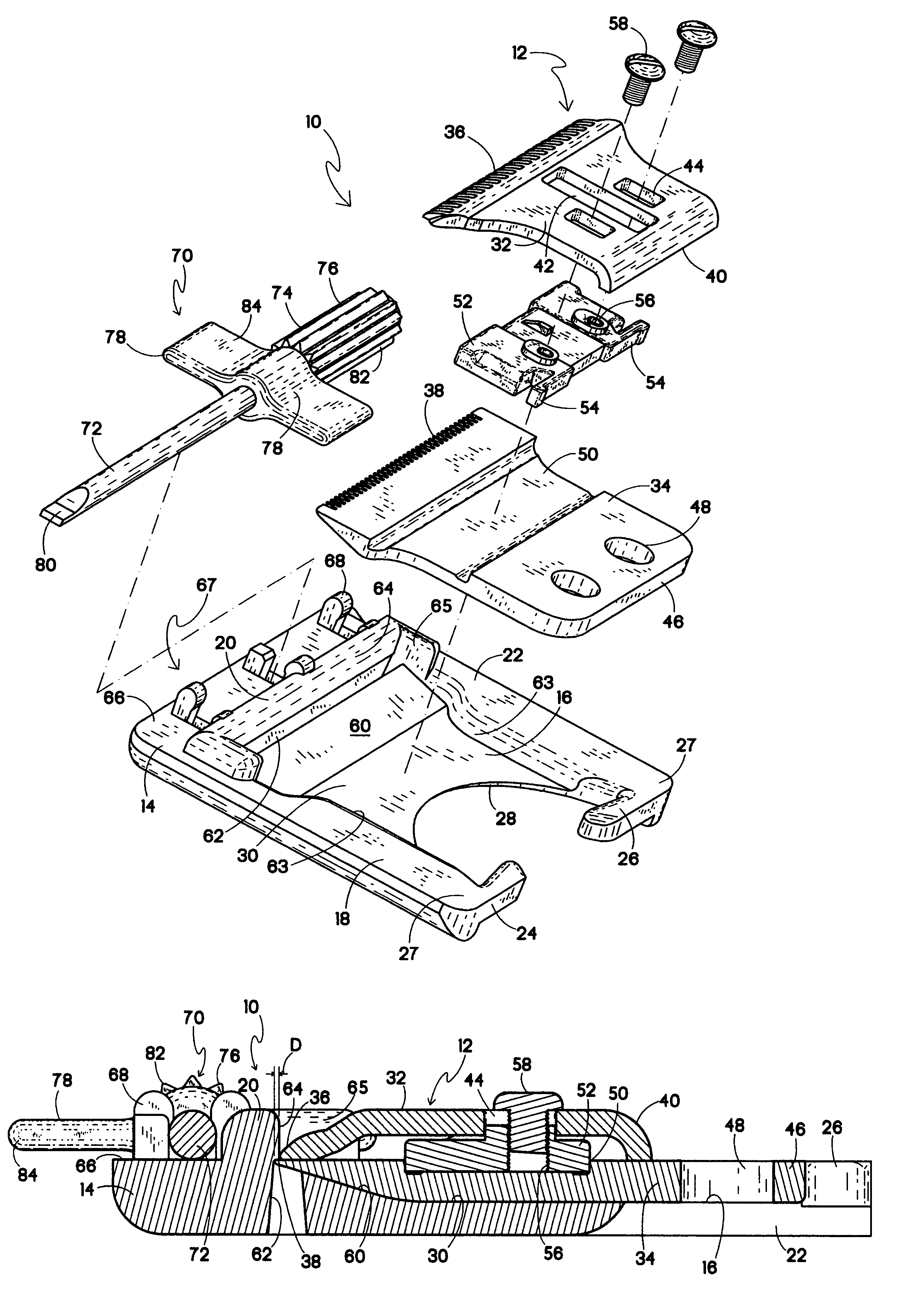
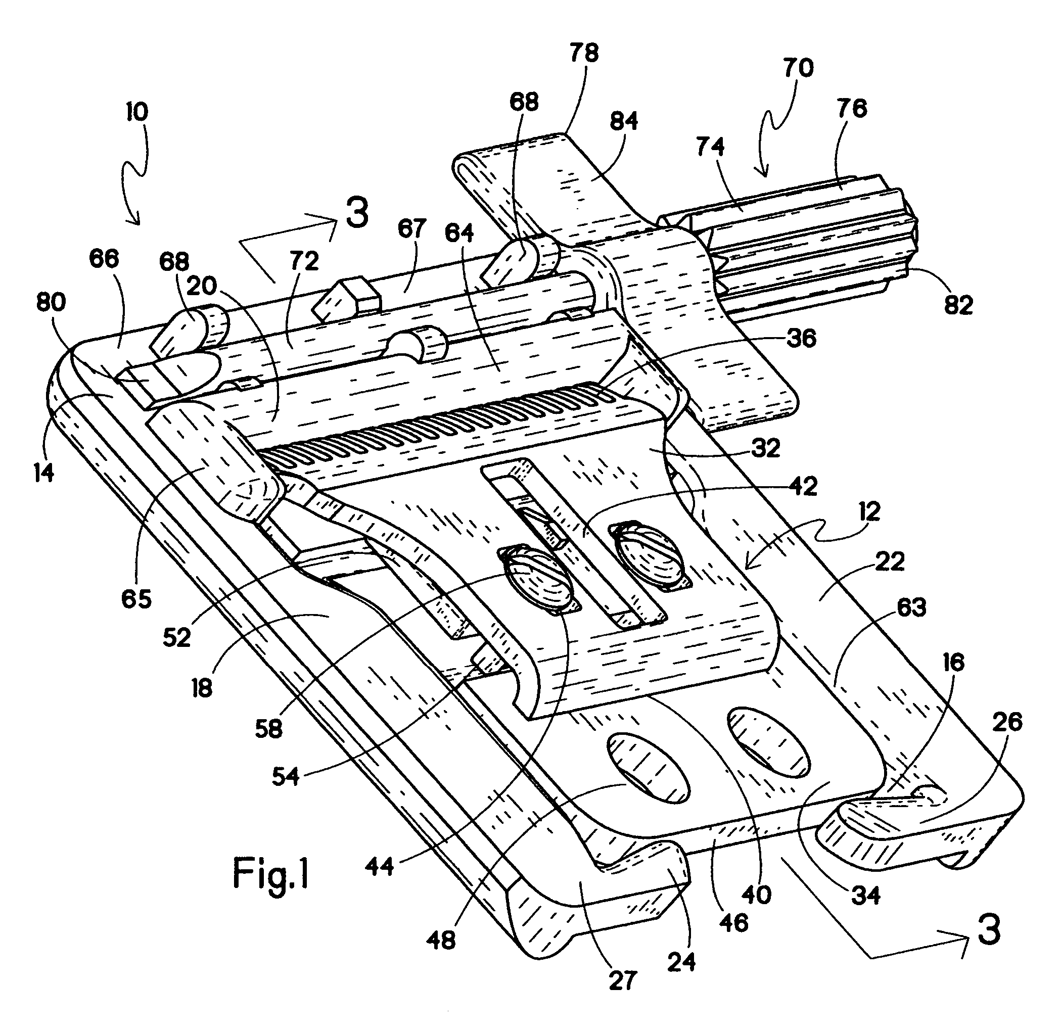
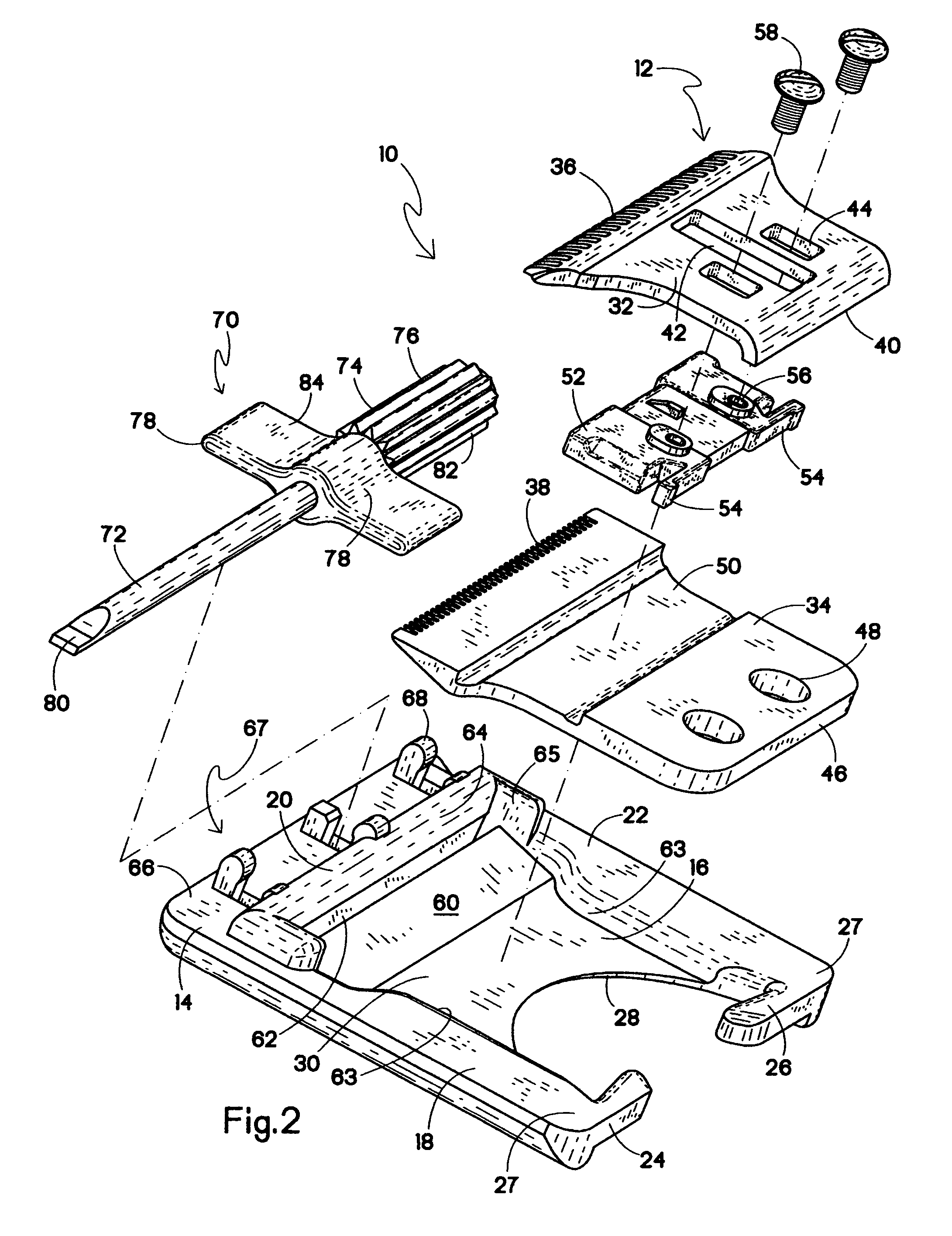
[0015]Referring to FIGS. 1 and 2, the present blade calibration gauge, generally designated 10 is shown holding a bladeset 12. The bladeset 12 is received by a base 14 in a recess 16 of the blade calibration gauge 10. The recess 16 is defined by a first side portion 18, a top section 20, and a second side portion 22. When viewed from above, the first and second side portions 18, 22 are in generally spaced parallel relationship to each other, and when combined with the top section 20, from a general “U”-shape. Alternate shapes for the recess 16 and the components defining the recess are contemplated as long as the bladeset 12 is securely retained.

[0016]Projections 24 and 26 are secured to free ends 27 of the first and second side portions 18, 22 and project normally from the side portions to close off a rear end of the recess 16. Also, the projections 24 and 26 are configured to assert a spring force against a stationary blade against a designated stop, and also to snugly retaining t...


PUM


Abstract

A blade calibration gauge for a bladeset for a hair cutter has a moving blade laterally reciprocating relative to a stationary blade, where the moving blade and the stationary blade are adjustable relative to one another in a direction normal to a direction of reciprocation. The blade calibration gauge has a base defining a recess configured for receiving the stationary blade and providing a first stop for engaging a toothed edge of the stationary blade, and a second stop on the base disposed relative to first stop for providing a designed offset spacing for a toothed cutting edge of the moving blade relative to the corresponding toothed edge of the fixed blade.

Description

BACKGROUND OF THE INVENTION[0001]The present invention relates generally hair cutting devices wherein the cutting action is obtained by reciprocating blades such as clippers and trimmers. More specifically, the present invention relates to devices for adjusting the spacing between blades in hair cutting devices (collectively referred to as hair cutters) having a bladeset with a moving blade and a stationary blade.[0002]In such bladesets, the moving blade laterally reciprocates relative to the stationary blade, and the moving and stationary blades are adjustable relative to one another in a direction normal to a direction of reciprocation. The distance between toothed ends of the blades is adjusted by releasing fasteners, which are typically screws, that connect the moving blade to a guide held by the stationary blade, and then adjusting the moving blade to the desired spacing. These screws must be sufficiently tightened so that they will not loosen when the clipper is in use.[0003]F...

Claims


Application Information

Patent Timeline
Patent Type & Authority Patents(United States)
IPC IPC(8): B27G23/00
CPCB25B15/02B25G1/105B26B19/38B26B19/3846B26B19/3826B26B19/06B26B19/20
Inventor MCCAMBRIDGE, JAMES E.LANGLEY, LUTHER D.
Owner WAHL CLIPPER
Why Eureka
Try Eureka