Method and apparatus for injecting steam into a geological formation

a geological formation and steam injection technology, applied in the direction of drilling casings, drilling pipes, borehole/well accessories, etc., can solve the problems of insufficient natural pressure in the hydrocarbon formation accessed by most wellbores to cause the hydrocarbons to rise to the surface, practical limitations, and expensive and time-consuming installation of apparatus, so as to achieve uniform steam pressure distribution

Inactive Publication Date: 2008-04-01
WEATHERFORD TECH HLDG LLC
View PDF21 Cites 55 Cited by
  • Summary
  • Abstract
  • Description
  • Claims
  • Application Information

AI Technical Summary

Problems solved by technology

The hydrocarbon formations accessed by most wellbores do not have adequate natural pressure to cause the hydrocarbons to rise to the surface on their own.
Because each wellbore includes production zones with varying natural pressures and permeabilities, the requirement for the injected steam can vary between zones, creating a problem when the steam is provided from a single source.
While this technique theoretically exposes each zone to steam, it has practical limitations since most of the steam enters the highest zone in the wellbore (the zone having the least natural pressure or the highest permeability).
Additionally, the apparatus is costly and time consuming to install due to the multiple, separate tubular strings 135, 140, 145.
The approach suffers the same problems as other prior art solutions in that the amount of steam entering each zone is difficult to control and some zones, because of their higher natural pressure or lower permeability, may not receive any steam at all.
While the regulation of steam is possible when a critical flow of steam is passed through a single nozzle or restriction, these devices are inefficient and a critical flow is not possible if a ratio of pressure in the annulus to pressure in the tubular becomes greater than 0.56.
Another disadvantage of the forgoing arrangements relates to ease of changing components and operating characteristics of the apparatus.
Because the nozzles are an integral part of a tubing string in the conventional arrangements, changing them requires removal of the string, an expensive and time-consuming operation.
Another problem with prior art injection methods involves the distribution of steam components.
Because the injection process relies upon an optimum mixture of steam components, changes in the relative proportions of water and vapor prior to entering the formations is a problem that affects the success of the injection job.
Additional problems are also encountered with injection methods involving lateral wellbores.
Because the injection is from the heel of the wellbore, the steam often has a higher pressure at the heel of the wellbore than at the toe due to pressure loss in the steam resulting from frictional resistance along the length of the wellbore as the steam travels downstream.
As a result, as steam travels along the horizontal wellbore, its pressure typically undesirably varies along the length of the wellbore.
Because the phases tend to separate, the steam injected into the zone of interest along the wellbore may not be uniform in phase components.

Method used


Image

  • Method and apparatus for injecting steam into a geological formation
  • Method and apparatus for injecting steam into a geological formation
  • Method and apparatus for injecting steam into a geological formation

Examples


Embodiment Construction

[0033]The present invention provides an apparatus and methods to inject steam into a geological formation from a wellbore.

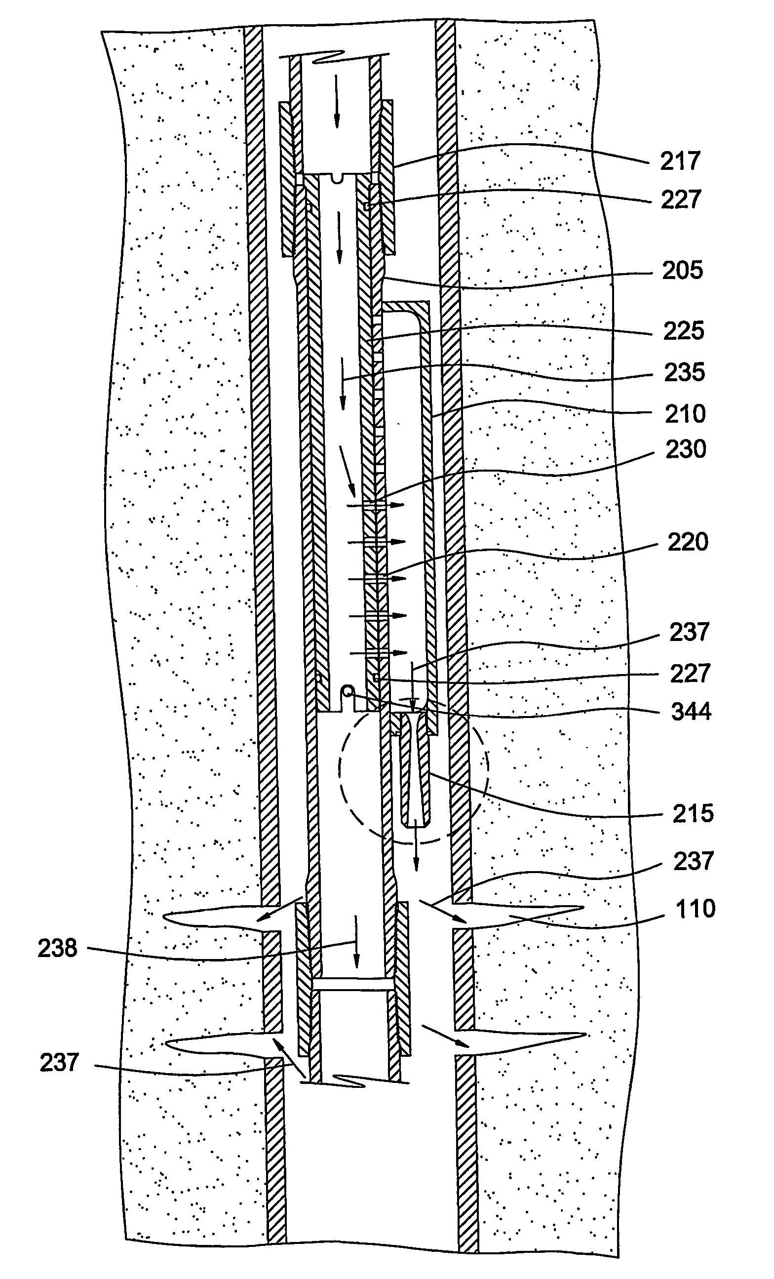
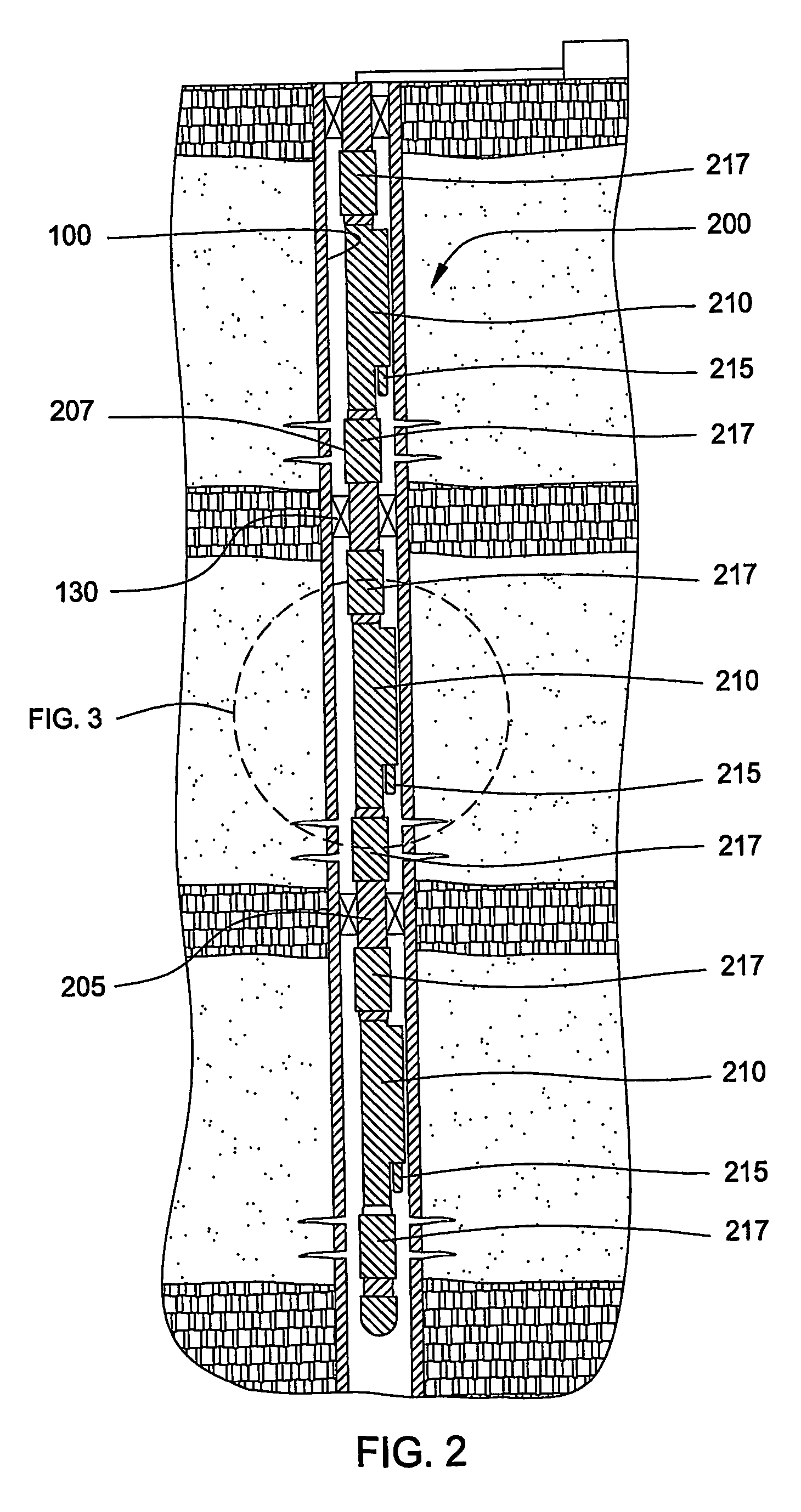
[0034]FIG. 2 is a section view of a vertical wellbore 100 illustrating an apparatus 200 of the present invention disposed in a wellbore. A string of tubulars 205 is coaxially disposed in the wellbore 100. In the embodiment of FIG. 2, the tubing string includes three enlarged area or pockets 210 formed therein, each of which define an annular area with the casing and include a nozzle 215 at one end. The apparatus is located in a manner whereby the pockets formed in the tubular are adjacent perforated sections of the casing. Each perforated area corresponds to a zone of the well to be injected with steam. Each pocket is preferably formed in a sub that can be located in the tubular string and then positioned adjacent a zone. Each nozzle provides fluid communication between the apparatus and a zone of interest. Each zone is isolated with packers 130 to ensure that st...


PUM


Abstract

The present invention generally provides a method and apparatus for injecting a compressible fluid at a controlled flow rate into a geological formation at multiple zones of interest. In one aspect, the invention provides a tubing string with a pocket and a nozzle at each isolated zone. The nozzle permits a predetermined, controlled flow rate to be maintained at higher annulus to tubing pressure ratios. In another aspect, the present invention assures that the fluid is supplied uniformly to a long horizontal wellbore by providing controlled injection at multiple locations that are distributed throughout the length of the wellbore. In another aspect, the invention ensures that saturated steam is injected into a formation in a predetermined proportion of water and vapor by providing a plurality of apertures between a tubing wall and a pocket.

Description

CROSS-REFERENCE TO RELATED APPLICATIONS[0001]This application is a continuation-in-part of U.S. patent application Ser. No. 10 / 097,448, filed Mar. 13, 2002, now U.S. Pat. No. 6,708,763, which is herein incorporated by reference.BACKGROUND OF THE INVENTION[0002]1. Field of the Invention[0003]The present invention relates to the production of hydrocarbon wells. More particularly the invention relates to the use of pressurized steam to encourage production of hydrocarbons from a wellbore. More particularly still, the invention relates to methods and apparatus to inject steam into a wellbore at a controlled flow rate in order to urge hydrocarbons to another wellbore.[0004]2. Description of the Related Art[0005]To complete a well for hydrocarbon production, a wellbore drilled in the earth is typically lined with casing which is inserted into the well and then cemented in place. As the well is drilled to a greater depth, smaller diameter strings of casing are lowered into the wellbore and...

Claims


Application Information

Patent Timeline
Patent Type & Authority Patents(United States)
IPC IPC(8): E21B43/24E21B41/00
CPCE21B41/0078E21B43/24
Inventor HOWARD, WILLIAM F.SIMS, JACKIE C.ROBINSON, DUDLEY L.SCHMIDT, RONALD W.
Owner WEATHERFORD TECH HLDG LLC
Why Eureka
Try Eureka