
Vehicle traction device

Inactive Publication Date: 2008-04-01
BRENNER EUGENE
View PDF9 Cites 20 Cited by
  • Summary
  • Abstract
  • Description
  • Claims
  • Application Information

AI Technical Summary

Benefits of technology

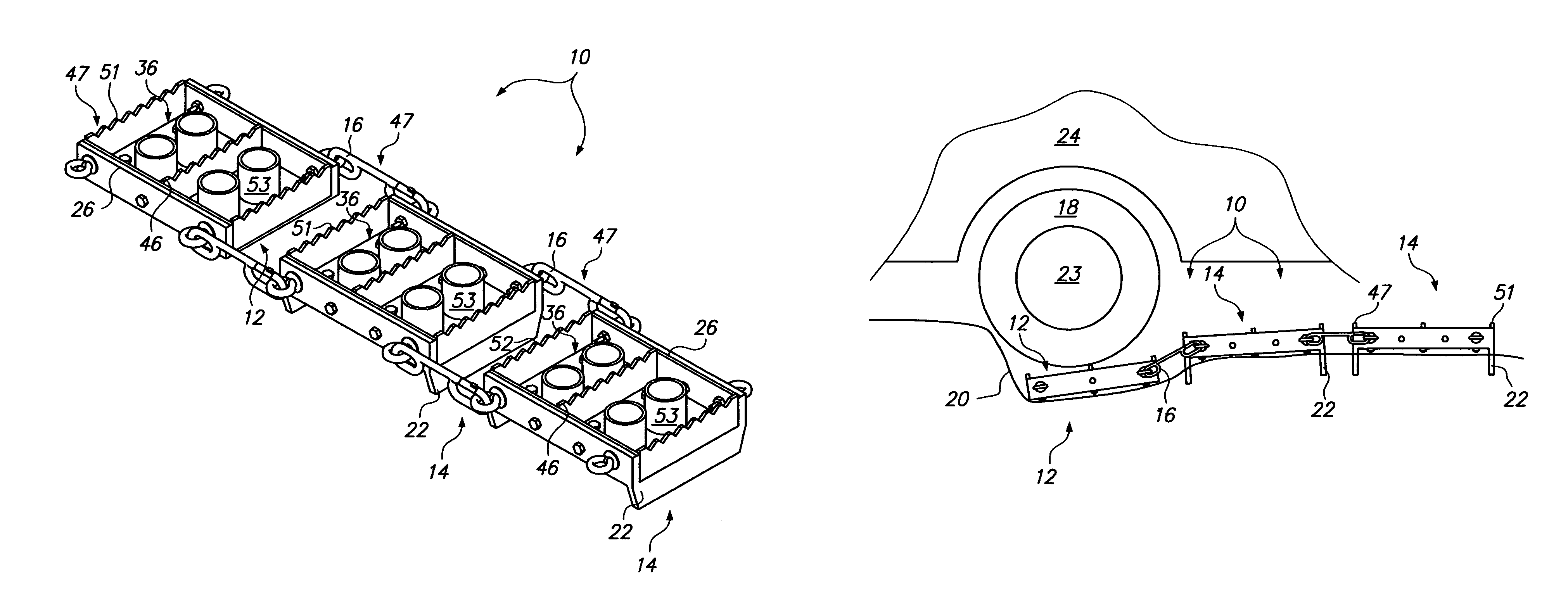
[0005]The inventive vehicle traction device is resistant to becoming overloaded with slippery surface materials, such as mud or snow, and especially performs well when a vehicle is mired in mud having a high clay content. The device is made from rigid materials and is modular in its design wherein at least two modules placed under a drive wheel are required to create an operational device. It is best if at least two modules are placed under each wheel of the drive axle to take advantage of the power transferring properties of the drive axle. The first module is of a low profile design which inserts under a drive wheel of a vehicle that is mired in mud, snow or sand. The second module is flexibly linked to the first module, the second module having deep anchoring fins which anchor the device in soft soil or sand.
[0007]Accordingly, the following objects and advantages of the invention apply:
[0008]It is an object of this invention to provide a vehicle traction device which resists becoming overloaded with slippery surface materials, especially mud having a high clay content.
[0009]It is another object of this invention to provide a vehicle traction device which can be stacked in a compact fashion so that it can be stored easily within a vehicle.

Problems solved by technology

A problem can arise when the traction surface becomes overloaded with mud, especially mud having a high clay content, which tends to fill up and stick to a traction surface.
Once filled, a traction surface loaded with high-clay mud can become as slick as the mud surface itself, rendering the traction surface useless.

Method used


Image

  • Vehicle traction device
  • Vehicle traction device
  • Vehicle traction device

Examples


Embodiment Construction

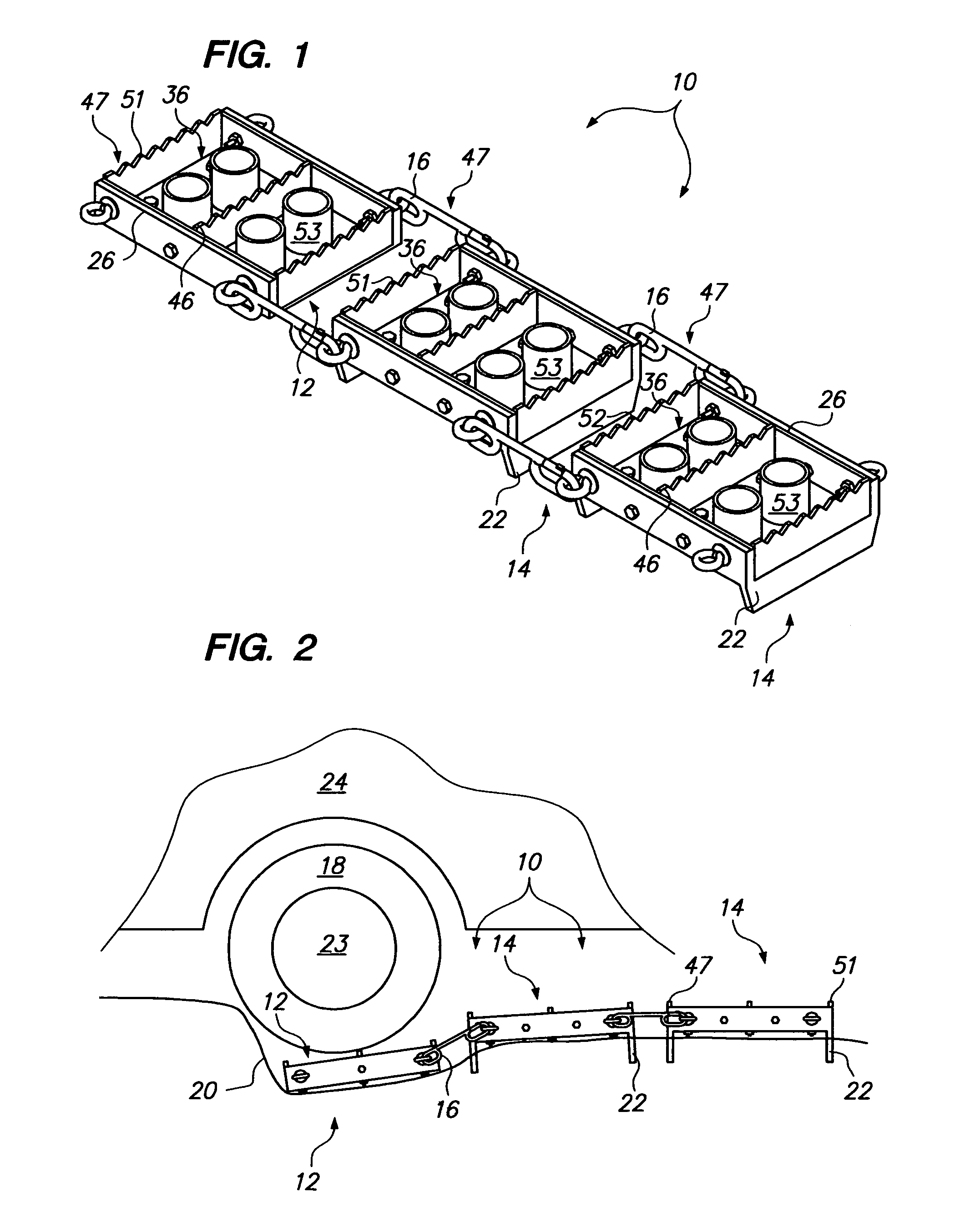
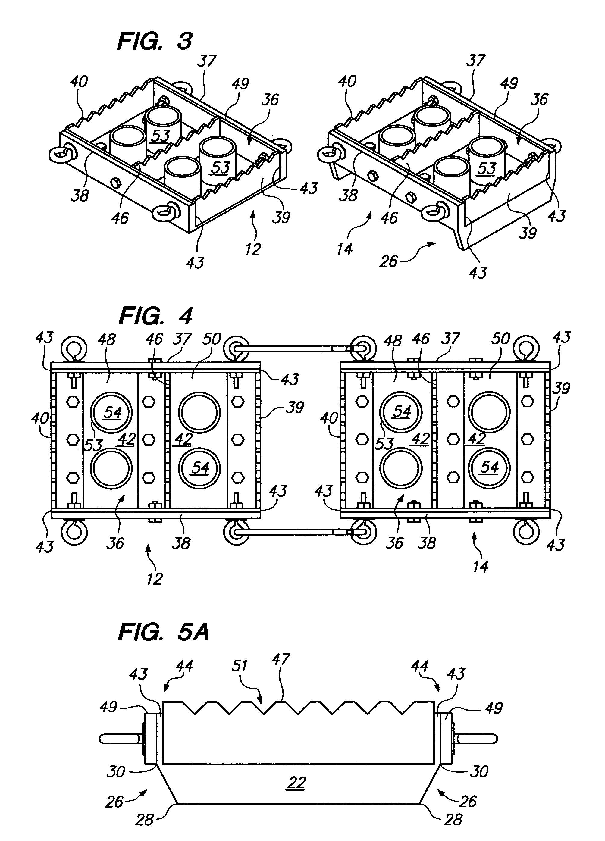
[0020]Referring to FIG. 1 the preferred embodiment of the inventive traction device 10 is shown. The device 10 is comprised of a plurality of modules 12, 14, which can be linked together indefinitely by a flexible link, such as a chain or releasable snap link 16. Preferred materials for constructing the device 10 are rigid materials such as aluminum, other metals or lightweight carbon fiber composites. The minimum number of required modules 12, 14 is two, to create an operative device 10, namely a low-profile module 12 which is inserted beneath the tire of a mired vehicle drive wheel, and a second high-profile module 14, which is anchored deeply into the soft surface material (e.g. mud, sand, or snow) to prevent the device 10 from being thrown out from beneath the spinning tire. FIG. 2. shows the device 10 represented as three modules 12, 14 in a typical configuration for extricating a vehicle's mired tire 18. The low profile module 12 fits within the mud hole 20 and beneath the tir...


PUM


Abstract

An inventive traction device is provided for extricating mired vehicles from mud, snow or sand. The device is comprised of modules linked together to create a track upon which a mired vehicle drives over. The individual modules each have four walls forming a trough and a number of tire supports which rise up from the floor of the trough. The trough-like construction of the device helps prevent the device from becoming overloaded with mud deposited from mired vehicle tires.

Description

TECHNICAL FIELD[0001]This invention relates to devices for removing a mired vehicle from mud holes, sand traps and snow banks, and more specifically, relates to a vehicle removal device which resists becoming overloaded with mud, sand or snow.BACKGROUND[0002]Traction devices for extricating a vehicle from mud holes, sand traps and snow banks are wide and varied. Many of these devices involve placing some sort of flat traction surface beneath the wheel of a vehicle, wherein the stuck vehicle climbs up on the traction surface, thereby extricating the vehicle from its predicament. A problem can arise when the traction surface becomes overloaded with mud, especially mud having a high clay content, which tends to fill up and stick to a traction surface. Once filled, a traction surface loaded with high-clay mud can become as slick as the mud surface itself, rendering the traction surface useless.[0003]Therefore, a need exists for a traction device which resists becoming overloaded with mu...

Claims


Application Information

Patent Timeline
IPC IPC(8): E01B23/00
CPCB60B39/12
Inventor BRENNER, EUGENE
Owner BRENNER EUGENE
Learn More