Pattern testing board and system

a technology of pattern testing and target system, applied in the field of pattern testing board, can solve the problem that none of the known target system provides detailed information as to the size of the beam

Inactive Publication Date: 2008-04-01
LIGHTSHOT SYST
View PDF33 Cites 3 Cited by
  • Summary
  • Abstract
  • Description
  • Claims
  • Application Information

AI Technical Summary

Problems solved by technology

None of the known target systems provide detailed information as to the size of the beam, the shape of the beam, and what portion of the beam has hit the target.

Method used


Image

  • Pattern testing board and system
  • Pattern testing board and system
  • Pattern testing board and system

Examples


Embodiment Construction

[0037]For the purpose of providing a background for the present invention, the system for simulating shooting sports described in U.S. Pat. Nos. 5,716,216 and 6,068,484 is summarized below. Both patents are assigned to the assignee of this application and are incorporated by reference herein. Reference numerals used in the previous applications have been maintained for consistency, however, for the purpose of brevity, some of the figures have been omitted.

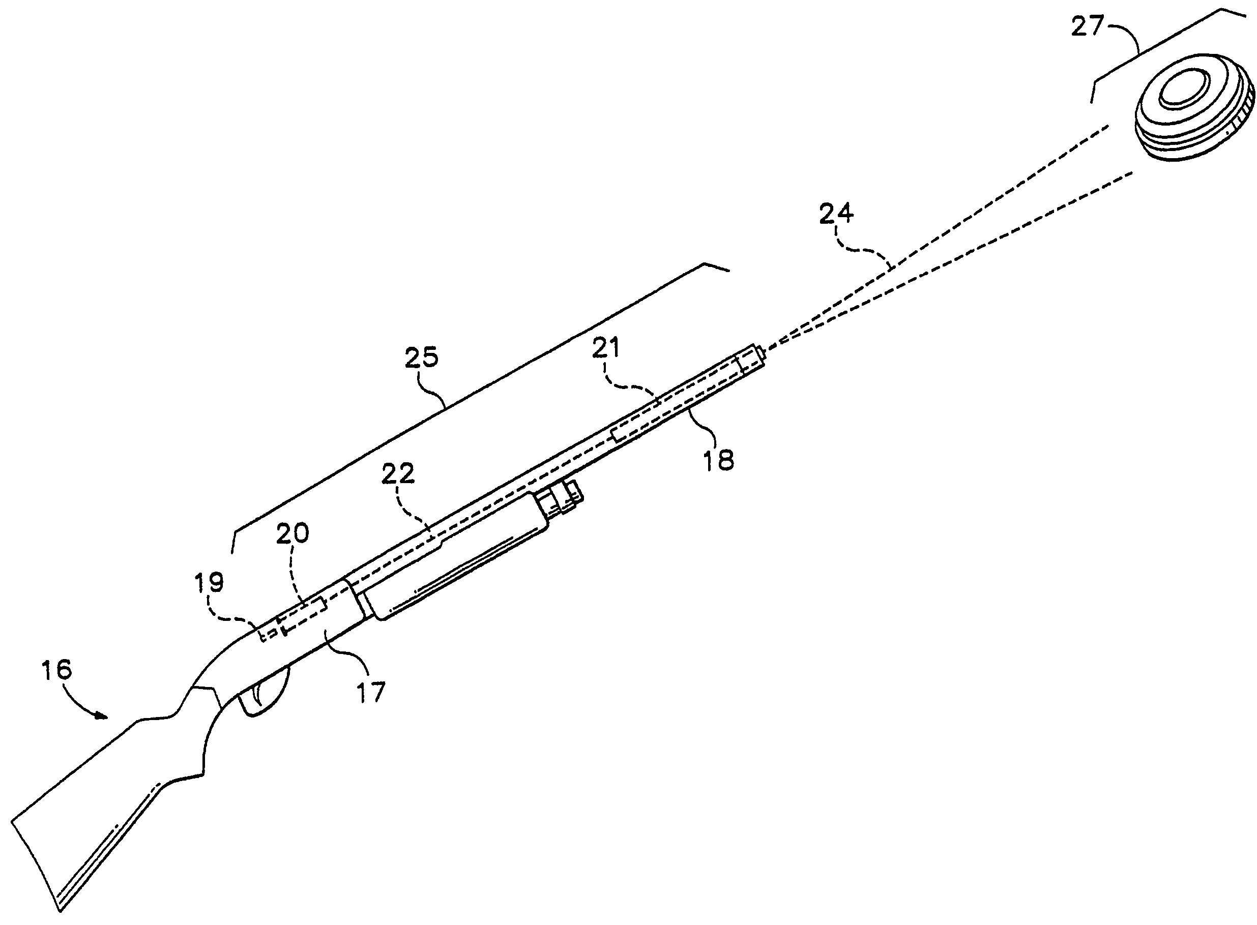
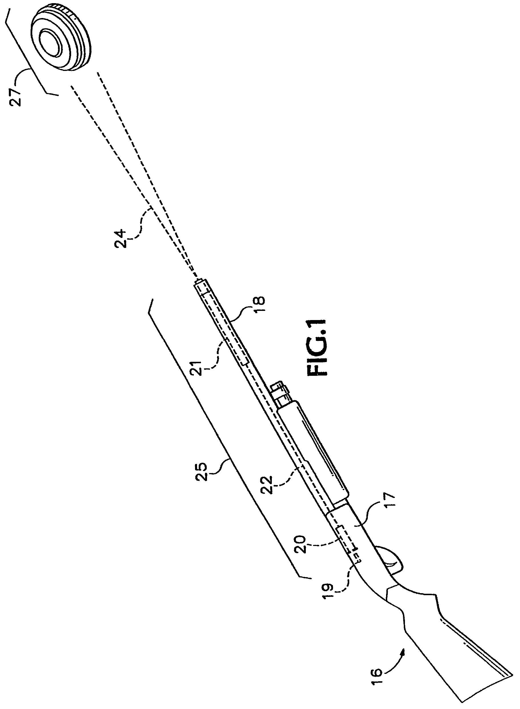
[0038]As shown in FIG. 1, a system for simulating shooting sports includes a non-projectile transmitter system 25 and a self-contained receiver system 27. The transmitter system 25 is retrofittable to any standard firearm 16 having an ammunition chamber 17, a barrel 18, and a firing pin 19.

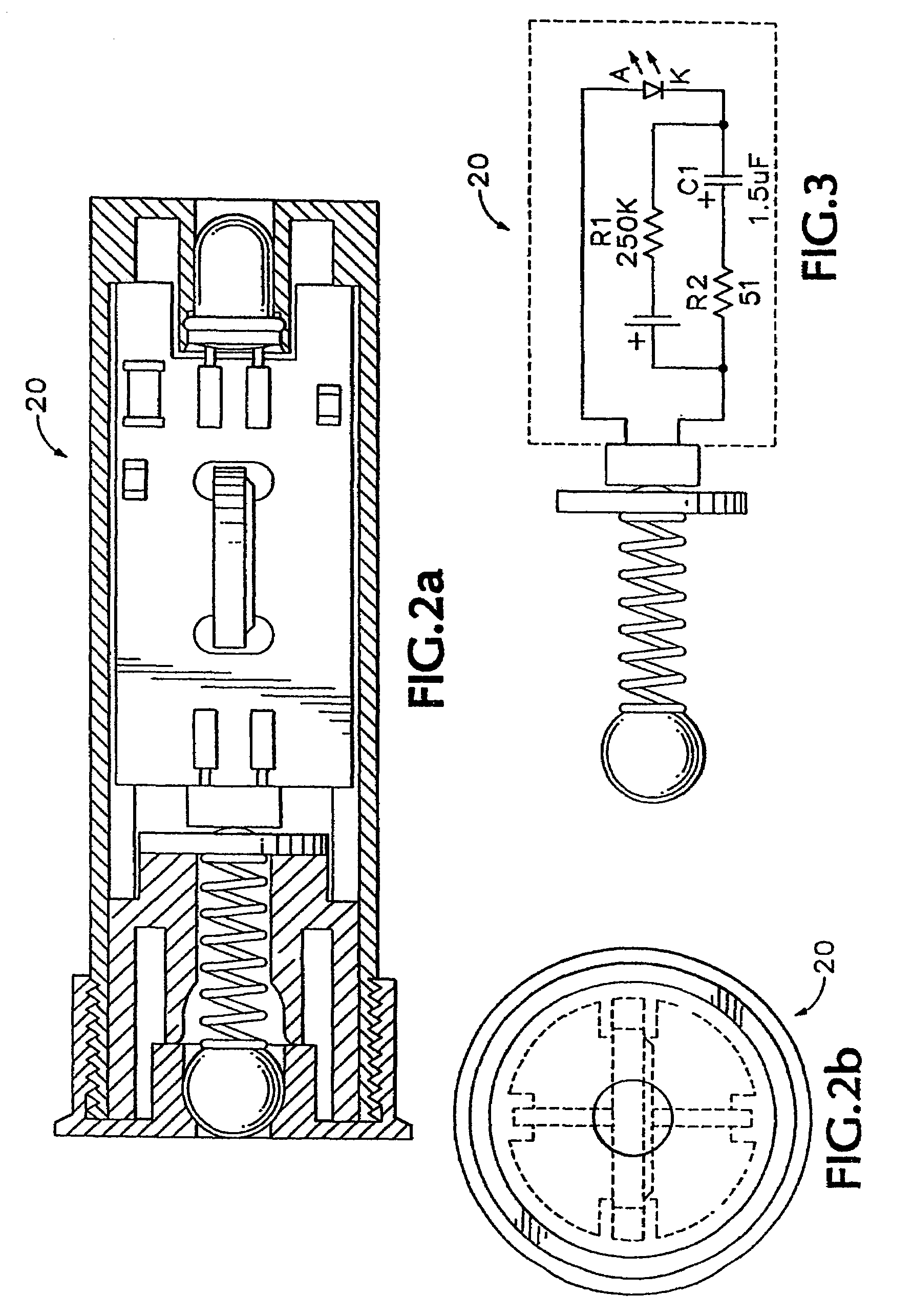
[0039]The transmitter system 25, as detailed in FIGS. 2-5, preferably includes an actuating beam (or wave) cartridge 20 and an adjustable beam (or wave) choke 21. The beam cartridge 20 has dimensions substantially identical to the dimensions of s...


PUM


Abstract

A pattern testing board is able to detect an emission beam such as a laser or light beam from a shooting system. A pattern testing board includes a plurality of paired emission beam sensors and hit indicators. Each emission beam sensor is responsive to a detected emission beam and each hit indicator signals the sensing of the emission beam by the associated emission beam sensor. Multiple pattern testing boards may be mounted together to provide a larger pattern testing system array. Further, an overlay with a representation thereon, a moving image display system, or a reflective moving image display system may be positioned in front of one or more pattern testing boards. Still further, the pattern testing board may be incorporated in a unique target system that includes the pattern testing board for determining the beam pattern emitted by the beam emitter, a level selection board for selecting a level of play, and a targeting game board having a plurality of targets.

Description

[0001]The present application is a continuation of U.S. patent application Ser. No. 10 / 919,551, now U.S. Pat. No. 6,960,085 filed Aug. 16, 2004. U.S. patent application Ser. No. 10 / 919,551 is a continuation of U.S. patent application Ser. No. 10 / 184,847, filed Jun. 27, 2002 (which issued as U.S. Pat. No. 6,780,014 on Aug. 24, 2004). U.S. patent application Ser. No. 10 / 184,847 claims the benefit under 35 USC Section 119(e) of U.S. Provisional Patent Application Ser. No. 60 / 309,360, filed Aug. 1, 2001. U.S. patent application Ser. No. 10 / 184,847 is a continuation-in-part application of U.S. patent application Ser. No. 09 / 222,337, filed Dec. 28, 1998 (now abandoned). U.S. patent application Ser. No. 09 / 222,337 is a continuation-in-part application of U.S. patent application Ser. No. 09 / 019,152, filed Feb. 6, 1998 (which issued as U.S. Pat. No. 6,068,484 on May 30, 2000). U.S. patent application Ser. No. 09 / 019,152 is a continuation of U.S. patent application Ser. No. 08 / 753,537, filed ...

Claims


Application Information

Patent Timeline
Patent Type & Authority Patents(United States)
IPC IPC(8): F41G3/26F41A33/02F41J5/02
CPCF41A33/02F41J5/02
Inventor HULL, GEORGE R.O'LOUGHLIN, SR., ROBERT M.O'LOUGHLIN, TERRY P.
Owner LIGHTSHOT SYST
Why Eureka
Try Eureka