Magnetic recording medium and magnetic recording and reproducing device using a magnetic recording layer formed with a predetermined concavo-convex pattern
a recording layer and recording medium technology, applied in the field of magnetic recording medium and magnetic recording recording and reproducing devices, can solve the problems of side fringes, crosstalk, etc., the improvement in the areal density using background-art techniques has reached its limit, and the gap length between the magnetic head and the magnetic recording layer is increased, so as to reduce the cost, prevent stiction, suppress the effect of the increase in frictional resistance between the magnetic recording medium and the head slider
- Summary
- Abstract
- Description
- Claims
- Application Information
AI Technical Summary
Benefits of technology
Problems solved by technology
Method used
Image
Examples
example 1
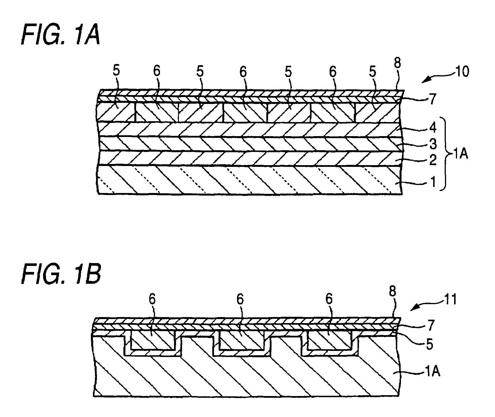
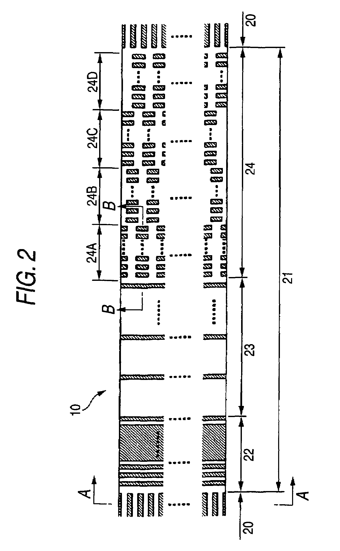
[0104]A non-magnetic layer 6 was formed on the to-be-processed body obtained in the aforementioned manner. First, a film of SiO2 was formed to be 100 nm thick by a sputtering method in the conditions of 500 W in film formation power, 150 W in bias power and 0.3 Pa in Ar gas pressure. Incidentally, the film thickness here means the thickness of a film on a flat surface when the film was formed on the flat surface in parallel. Ion beam etching using Ar gas and having an incident angle of 2° was performed on the to-be-processed body after the non-magnetic layer 6 was formed. Thus, a surplus of SiOs on the magnetic recording layer 5 was removed so that the surface was flattened. The etching was monitored by a mass spectroscope. The flattening was completed as soon as the magnetic recording layer in the data track region 20 began to be detected.
[0105]Incidentally, the surface position of the non-magnetic layer 6 is lower in each servo pattern region 21 than in each data track region 20 w...
example 2
[0111]A magnetic recording medium shown in FIGS. 4A-4B was manufactured in a method similar to that in Example 1. This magnetic recording medium could be manufactured as follows. That is, in the ion beam etching of the non-magnetic layer in Example 1, the ion beam etching had been suspended since the magnetic recording layer 5 in each servo pattern region 21 began to be detected and till the magnetic recording layer 5 in each data track region 20 began to be detected. Thus, flattening was completed.
example 3
[0112]A magnetic recording medium shown in FIGS. 5A-5B was manufactured in a method similar to that in Example 1. This magnetic recording medium could be manufactured as follows. That is, in the ion beam etching of the non-magnetic layer in Example 1, the ion beam etching was once suspended as soon as the magnetic recording layer 5 in each servo pattern region 21 began to be detected. The incident angle was changed from 2° to 90° (90° was an incident angle with which “the etching rate of the magnetic recording layer 5 was higher than the etching rate of the non-magnetic material (SiO2)”), and the ion beam etching was resumed. The ion beam etching was suspended as soon as the magnetic recording layer 5 in each data track region 20 began to be detected. Thus, flattening was completed.
PUM
| Property | Measurement | Unit |
|---|---|---|
| thickness | aaaaa | aaaaa |
| thickness | aaaaa | aaaaa |
| thickness | aaaaa | aaaaa |
Abstract
Description
Claims
Application Information
 - R&D
- Intellectual Property
- Life Sciences
- Materials
- Tech Scout
- Unparalleled Data Quality
- Higher Quality Content
- 60% Fewer Hallucinations
Browse by: Latest US Patents, China's latest patents, Technical Efficacy Thesaurus, Application Domain, Technology Topic, Popular Technical Reports.
© 2025 PatSnap. All rights reserved.Legal|Privacy policy|Modern Slavery Act Transparency Statement|Sitemap|About US| Contact US: help@patsnap.com


