Contoured check valve disc and scroll compressor incorporating same

a technology of check valve disc and scroll compressor, which is applied in the direction of functional valve types, machines/engines, liquid fuel engines, etc., can solve the problem of reversed high-pressure compressed refrigerant, and achieve the effect of improving the structure of the check valv

Active Publication Date: 2012-12-11
BITZER KUEHLMASCHINENBAU GMBH
View PDF43 Cites 7 Cited by
  • Summary
  • Abstract
  • Description
  • Claims
  • Application Information

AI Technical Summary

Benefits of technology

[0006]In accordance with the present invention, such static cohesion is prevented by means for preventing static cohesion sticking force between the valve disc and the retainer (e.g. as may be provided by a stop plate of such a check valve) for such a check valve in a scroll compressor apparatus. Such means includes a minimal surface contact that prevents stiction. Such a minimum contact may be created by a relief region formed along the contact interface between the retainer and the valve disc which may be provided by a recessed region on either or both of the structures, but preferably on the valve disc.
[0007]In accordance with one aspect of the present invention, a compressor apparatus for the compression of fluid comprises a housing and scroll compressors bodies in the housing that have respective bases and scroll ribs that project from the respective bases and in which mutually engage. Relative movement between the scroll compressor bodies compress fluid through a discharge port. A high pressure chamber in the housing is arranged to receive compressed fluid from the scroll compressor bodies. A check valve includes a check valve chamber interposed between the high pressure chamber in the housing and the discharge port of the scroll compressor bodies. The check valve includes a valve disc (also referred to as a valve plate) and a retainer (such as a stop plate) that retains the valve disc within the valve chamber. The valve disc is moveable between a valve seat in a closed position and the valve retainer in an open position. A means is provided for preventing a static cohesion sticking force between the valve disc and the retainer.
[0008]In accordance with the above aspect, the compressor apparatus may generate a mist of lubricant used for lubrication within the scroll compressor which may create a lubricant film on the valve disc or the retainer which would ordinarily create the static cohesion sticking force. The means to prevent such static cohesion sticking force may comprise less then complete contact interface between the valve disc and the retainer. More specifically, such means may include a relieved portion along the contact interface between the retainer and the valve disc. According to certain embodiments, the valve disc may be dished to include an outer annular contact ring located in a contact plane and in which the contact ring engages the retainer along a contact plane in the open position while the relieved region is formed into the valve disc such as a concave structure and is fully surrounded by the contact ring. This minimizes the contact interface between the valve disc and the retainer.
[0010]Another inventive aspect is directed towards a check valve including a check valve housing having a check valve chamber extending between a retainer and a valve seat and in surrounding relation of a fluid port. The check valve also includes a valve disc that is retained by the retainer within the valve chamber. The valve disc is moveable between the valve seat in a closed position preventing back flow through the fluid port and the valve retainer in an open position permitting fluid flow through the fluid port and around the valve disc. A less than complete contact interface is provided between the valve disc and the retainer to prevent static cohesion sticking force between the valve disc and the retainer. Such a less than complete contact interface may be provided, for example, by a relieved portion that is provided along the contact interface between the retainer and the valve disc.

Problems solved by technology

This can create the risk that high-pressure compressed refrigerant may reverse flow around the check valve disc through the peripheral ports and back through the check valve; this can reverse the relative movement between the scroll compressor bodies when the scroll compressor unit is shut off.

Method used


Image

  • Contoured check valve disc and scroll compressor incorporating same
  • Contoured check valve disc and scroll compressor incorporating same
  • Contoured check valve disc and scroll compressor incorporating same

Examples


Embodiment Construction

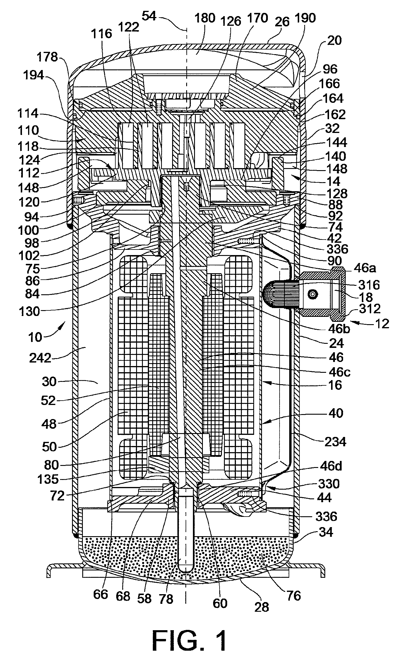
[0022]An embodiment of the present invention is illustrated in the figures as a scroll compressor assembly 10 generally including an outer housing 12 in which a scroll compressor 14 can be driven by a drive unit 16. The scroll compressor assembly may be arranged in a refrigerant circuit for refrigeration, industrial cooling, freezing, air conditioning or other appropriate applications where compressed fluid is desired. Appropriate connection ports provide for connection to a refrigeration circuit and include a refrigerant inlet port 18 and a refrigerant outlet port 20 extending through the outer housing 12. The scroll compressor assembly 10 is operable through operation of the drive unit 16 to operate the scroll compressor 14 and thereby compress an appropriate refrigerant or other fluid that enters the refrigerant inlet port 18 and exits the refrigerant outlet port 20 in a compressed high pressure state.

[0023]The outer housing 12 may take many forms. In the preferred embodiment, th...


PUM


Abstract

A check valve is provided which may be integrated into a scroll compressor that prevents static cohesion sticking forces between a valve disc member and a retainer member of the check valve housing. Such static cohesion sticking forces may be particularly generated due to oil mist generation in such scroll compressors which create a thin lubricant film between the valve disc and the stop plate of the check valve housing, creating suction type static cohesion when dislodgment of the valve disc away from the stop plate is attempted. A relief region is created between the retainer and the valve disc creating a minimal contact surface area that greatly reduces and / or eliminates such static cohesion sticking forces. For example, the valve disc may be dished to have a concave surface that faces the retainer element provided by the stop plate.

Description

FIELD OF THE INVENTION[0001]The present invention relates to check valves and / or scroll compressors for compressing refrigerant and more particularly relates to the check valves for such scroll compressors.BACKGROUND OF THE INVENTION[0002]A scroll compressor is a certain type of compressor that is used to compress refrigerant for such applications as refrigeration, air conditioning, industrial cooling and freezer applications, and / or other applications where compressed fluid may be used. Such prior scroll compressors are known, for example, as exemplified in U.S. Pat. No. 6,398,530 to Hasemann; U.S. Pat. No. 6,814,551, to Kammhoff et al.; U.S. Pat. No. 6,960,070 to Kammhoff et al.; and U.S. Pat. No. 7,112,046 to Kammhoff et al., all of which are assigned to a Bitzer entity closely related to the present assignee. As the present disclosure pertains to improvements that can be implemented in these or other scroll compressor designs, the entire disclosures of U.S. Pat. Nos. 6,398,530; ...

Claims


Application Information

Patent Timeline
Patent Type & Authority Patents(United States)
IPC IPC(8): F04C2/00F16K15/00F04C2/063F16K21/00
CPCF04C18/0215F04C23/008F04C29/126F16K15/023F04C29/0021F04C2270/12Y10T137/7898Y10T137/7914F04C18/02F04C29/12F16K15/02
Inventor WILSON, FRANCIS P.
Owner BITZER KUEHLMASCHINENBAU GMBH
Why Eureka
Try Eureka