Encoder-equipped sealing device

a sealing device and encoder technology, applied in the direction of engine sealing, shaft and bearing components, bearing components, etc., can solve the problems of difficult removal of units, affecting the working efficiency of the fitting device, and the fitting device to become non-operational, so as to achieve the effect of high reliability

Inactive Publication Date: 2008-01-24
YAMAMOTO
View PDF6 Cites 0 Cited by
  • Summary
  • Abstract
  • Description
  • Claims
  • Application Information

AI Technical Summary

Benefits of technology

[0019] In order to eliminate serious disadvantages and problems associated with the prior art encoder-equipped sealing devices described above, it is an object of the present invention to provide an encoder-equipped sealing device that has a simple construction and prevents cohesion by magnetic attraction that might otherwise occur between two units of the encoder-equipped sealing device that are located adjacent each other. That is to say, the object of the present invention is to provide encoder-equipped sealing devices by which an encoder-equipped sealing device can be removed from a magazine without being caught by another encoder-equipped sealing device, and then may be mounted securely on an area that needs to be sealed, such as an appropriate area in a bearing unit, even if plural units of the encoder-equipped sealing device are placed one over another such that they are oriented in one particular direction, as shown in FIG. 8, and loaded in a magazine.
[0034] In any of the first, second, third, fourth and sixth embodiments of the present invention, when plural units of the encoder-equipped sealing device of the present invention are placed one over another adjacent each other so that they are oriented in one particular direction, for example, when two units 51, 52 of the encoder-equipped sealing device are placed one over another adjacent each other so that they are oriented in one particular direction as shown in FIG. 1, these two adjacent units 51 and 52 can be kept spaced away from each other by the cylindrical portion or flange portion of the metal core. This can maintain a gap between the two adjacent units 51 and 52 constant, and physical cohesion by magnetic attraction that would occur between the two units 51 and 52 can thus be prevented effectively.
[0035] In the fifth embodiment, when plural units of the encoder-equipped sealing device of the present invention are placed one over another adjacent each other so that they are oriented in one particular direction, for example, when two units 51, 52 of the encoder-equipped sealing device are placed one over the other adjacent each other so that they are oriented in one particular direction as shown in FIG. 1, an area of contact between the encoder and the flange portion of the metal core can be kept as small as possible, and physical cohesion by magnetic attraction that would occur between the two units can thus be prevented effectively.
[0036] In the seventh embodiment, when plural units of the encoder-equipped sealing device of the present invention are placed one over another adjacent each other so that they are oriented in one particular direction, for example, when two units 51, 52 of the encoder-equipped sealing device are placed one over the other adjacent each other so that they are oriented in one particular direction as shown in FIG. 1, a gap between these two adjacent units can be kept constant by the elastic lateral side portion 5 having the undulations 4g formed thereon, and physical cohesion by magnetic attraction that would occur between the two units can thus be prevented effectively.
[0037] It may be understood from the above description that when plural units of the encoder-equipped sealing device of the present invention are placed one over another so that they are oriented in one particular direction as shown in FIG. 1, cohesion by magnetic attraction that might otherwise occur between adjacent units can be prevented effectively. Accordingly, even if the plural units of the encoder-equipped sealing device are loaded in a magazine, with the units being placed one over another so that they are oriented in one particular direction, each encoder-equipped sealing device can be removed from the magazine without being caught by an adjacent encoder-equipped sealing device, and can then be mounted securely onto an area that needs to be sealed, such as an appropriate area in a bearing unit.
[0038] That is to say, even if plural units of the encoder-equipped sealing device are placed one over another so that they are oriented in one particular direction, each encoder-equipped sealing device can be slid relative to an adjacent encoder-equipped sealing device without causing any problems. Also, either of these two units that are located adjacently can be moved away from the other without causing any problems, so that each of the encoder-equipped sealing devices can be handled after being detached. Thus, the encoder-equipped sealing device of the present invention can be slid smoothly out of a magazine equipped in a fitting tool, without causing any problems such as being caught or stuck. Thus, the encoder-equipped sealing device can be mounted on an area that needs to be sealed, such as an appropriate area in a bearing unit, with highest reliability.

Problems solved by technology

When such cohesion occurs, the two units may attract each other magnetically within the magazine, from which it is difficult to remove the units by using any appropriate fitting device that mounts the units on an area that needs to be sealed, such as an appropriate area in a bearing unit.
This may cause the fitting device to become non-operational or may affect a working efficiency of the fitting device remarkably.
As this projection is formed as part of an elastic seal portion, the projection thus obtained is not sufficient to prevent cohesion by magnetic attraction that occurs between the two units.

Method used


Image

  • Encoder-equipped sealing device
  • Encoder-equipped sealing device
  • Encoder-equipped sealing device

Examples


first embodiment

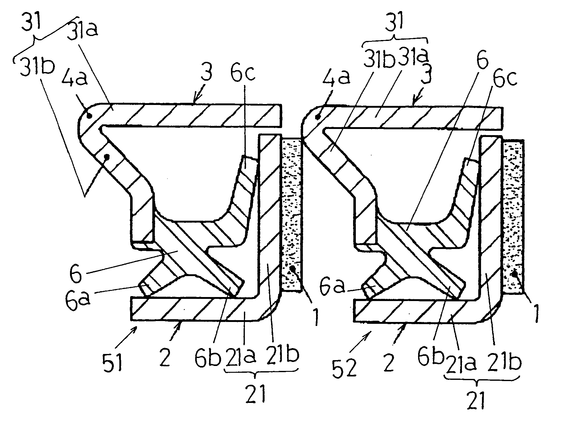
[0049] Referring first to FIG. 1, an encoder-equipped sealing device according to the present invention is described. In encoder-equipped sealing devices 51 and 52, seal element 3 includes a projecting portion 4a on an end of cylindrical portion 31a on a side on which flange portion 31b is located. The projecting portion 4a extends beyond a side of the flange portion 31b opposite a side on which seal portion 6 is located and in a direction in which the cylindrical portion 31a extends. That is to say, the projecting portion 4a extends beyond the left side of the flange portion 31b in FIG. 1.

[0050] In the embodiment shown in FIG. 1, an end of the cylindrical portion 31a that is located on the left side and a base end of the flange portion 31b are formed in such a manner as to extend toward the left side. This before described portion extends toward the left side in FIG. 1 and forms the projecting portion 4a.

[0051] Referring next to FIG. 2, an encoder-equipped sealing device according...

third embodiment

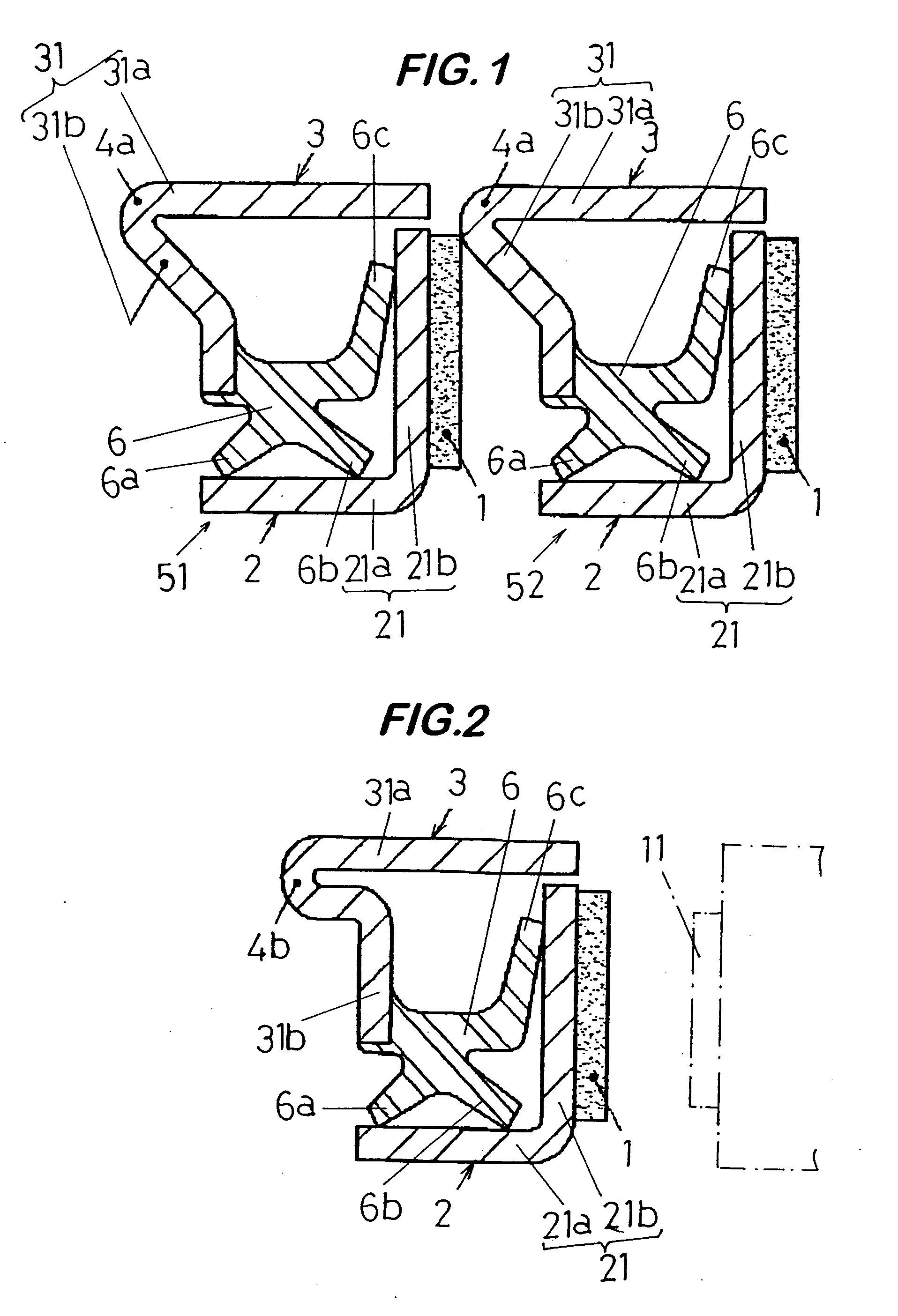
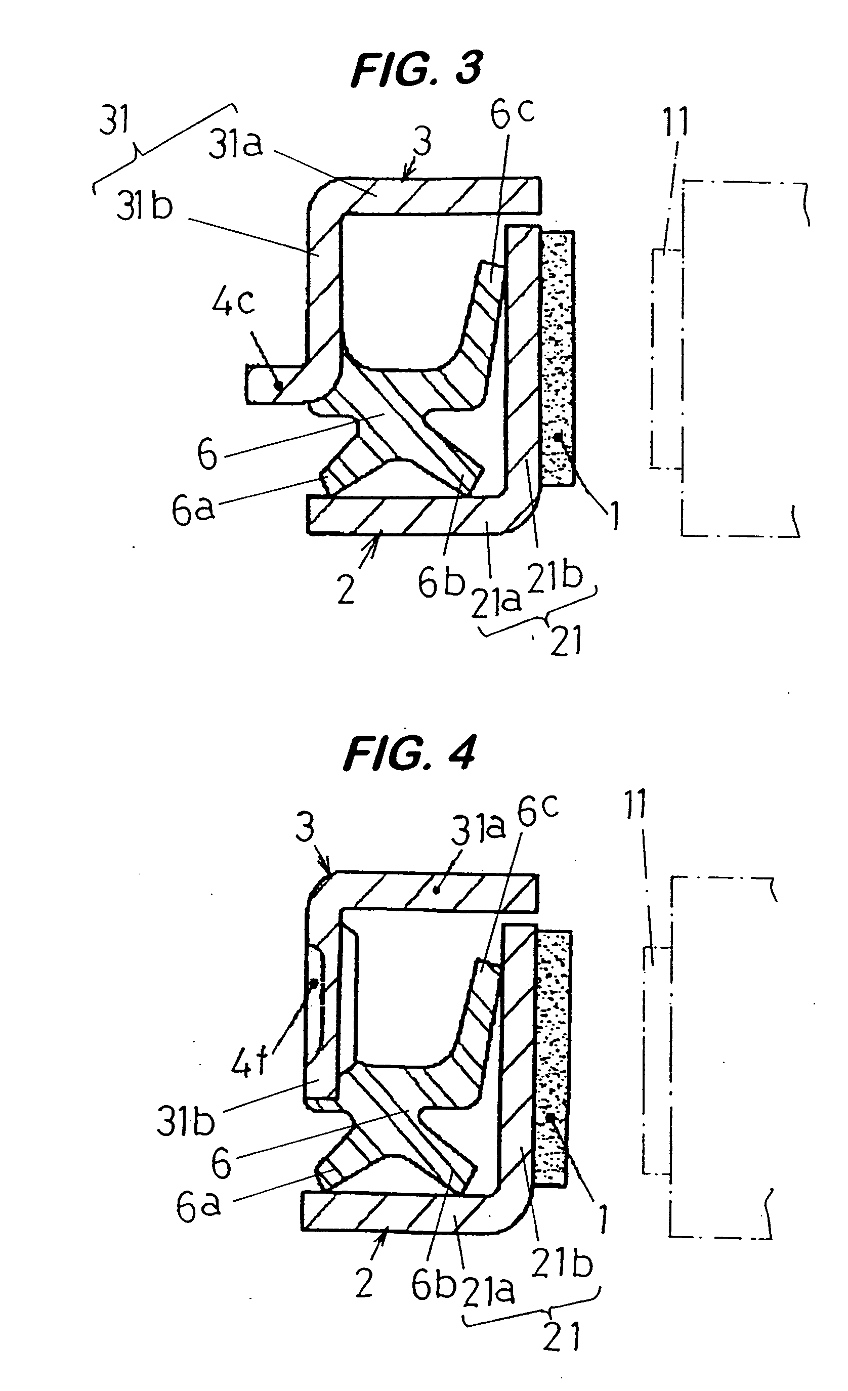
[0053] Referring next to FIG. 3, an encoder-equipped sealing device according to the present invention is described.

[0054] In the encoder-equipped sealing device shown in FIG. 3, seal element 3 includes a projecting portion 4c extending beyond a side of flange portion 31b opposite a side on which seal portion 6 is located and extending in a direction in which cylindrical portion 31a extends. That is to say, the projecting portion 4c extends beyond the left side of the flange portion 31b in FIG. 3.

[0055] In the third embodiment shown in FIG. 3, the projecting portion 4c is formed by bending an end of the flange portion 31b toward the left side in FIG. 3. It should be noted that this embodiment may be varied such that the projecting portion 4c can be located on a middle portion of the flange portion 31b.

fourth embodiment

[0056] Referring next to FIG. 5, an encoder-equipped sealing device according to the present invention is described.

[0057] In the encoder-equipped sealing device shown in FIG. 5, end portion 4d of cylindrical portion 31a of the seal element 3 extending toward another seal element 2 extends in a direction in which the cylindrical portion 31a extends. And, the end portion 4d further extends beyond a side of the other seal element 2 opposite the side on which the other seal element 2 faces opposite the seal element 3. That is to say, the end portion 4d of the cylindrical portion 31a of the seal element 3 extends beyond the right side of the seal element 2 in the direction in which the cylindrical portion 31a extends.

[0058] In the fourth embodiment shown in FIG. 5, an encoder 1 is arranged on a side (right side in FIG. 5) of flange portion 21b opposite a side on which the flange portion 21b faces the seal element 3. Since the end portion 4d of the cylindrical portion 31a of the seal el...


PUM


Abstract

An encoder-equipped sealing device, that is, a sealing device that has an encoder incorporated therein is disclosed, which comprises a combination of seal elements, each of which includes an annular metal core having a substantially L-shaped cross section and including a cylindrical portion and a flange portion provided on one end of the cylindrical portion and extending in a direction perpendicular to a direction in which the cylindrical portion extends. One seal element, of the two seal elements, and the other seal element are combined such that a space defined by the cylindrical portion and flange portion of the one seal element, and a space defined by the cylindrical portion and flange portion of the other seal element, face opposite each other, wherein the one seal element further includes an elastic seal portion provided on the flange portion and arranged in the space defined by the cylindrical portion and flange portion, and the other seal element further includes a magnet-based encoder provided on the flange portion. The one seal element further includes a projecting portion on an end of the cylindrical portion on a side on which the flange portion is located and extending beyond a side of the flange portion opposite a side on which the seal portion is located and in a direction in which the cylindrical portion extends.

Description

[0001] This application is a continuation of U.S. Ser. No. 11 / 500,402, filed Aug. 6, 2006, which is a continuation of U.S. Ser. No. 10 / 690,550, filed Oct. 23, 2003.BACKGROUND [0002] 1. Field of the Invention [0003] The present invention relates to an improvement to and / or in an encoder-equipped sealing device or sealing device that has a magnet-based encoder incorporated therein. More particularly, the present invention relates to such encoder-equipped sealing device that provides capabilities for preventing physical cohesion by magnetic attraction from occurring between two or more units of encoder-based sealing devices that are adjacent to each other, when these units are placed one over another so that they are oriented in one particular direction. [0004] 2. Description of the Prior Art [0005] An encoder (pulse coder) that is incorporated in the encoder-equipped sealing device that has been described above takes the form of a pulse generator ring that may be mounted on an automot...

Claims


Application Information

Patent Timeline
Patent Type & Authority Applications(United States)
IPC IPC(8): F16J15/00F16C33/78F16J15/3232F16J15/326F16J15/3264
CPCF16J15/326F16C41/007F16C33/7883
Inventor YAMAMOTO, HIRONORI
Owner YAMAMOTO
Why Eureka
Try Eureka