
Electrode binder solution composition for polymer electrolyte fuel cell

a fuel cell and electrolyte technology, applied in the direction of cell components, basic electric elements, electrochemical generators, etc., can solve the problems of reducing the performance of electrodes and mea, depleting fossil energy resources within years, etc., to improve electrode activity, increase the active surface area of electrodes, and prevent cohesion

Inactive Publication Date: 2009-11-12
HYUNDAI MOTOR CO LTD +1
View PDF1 Cites 1 Cited by
  • Summary
  • Abstract
  • Description
  • Claims
  • Application Information

AI Technical Summary

Benefits of technology

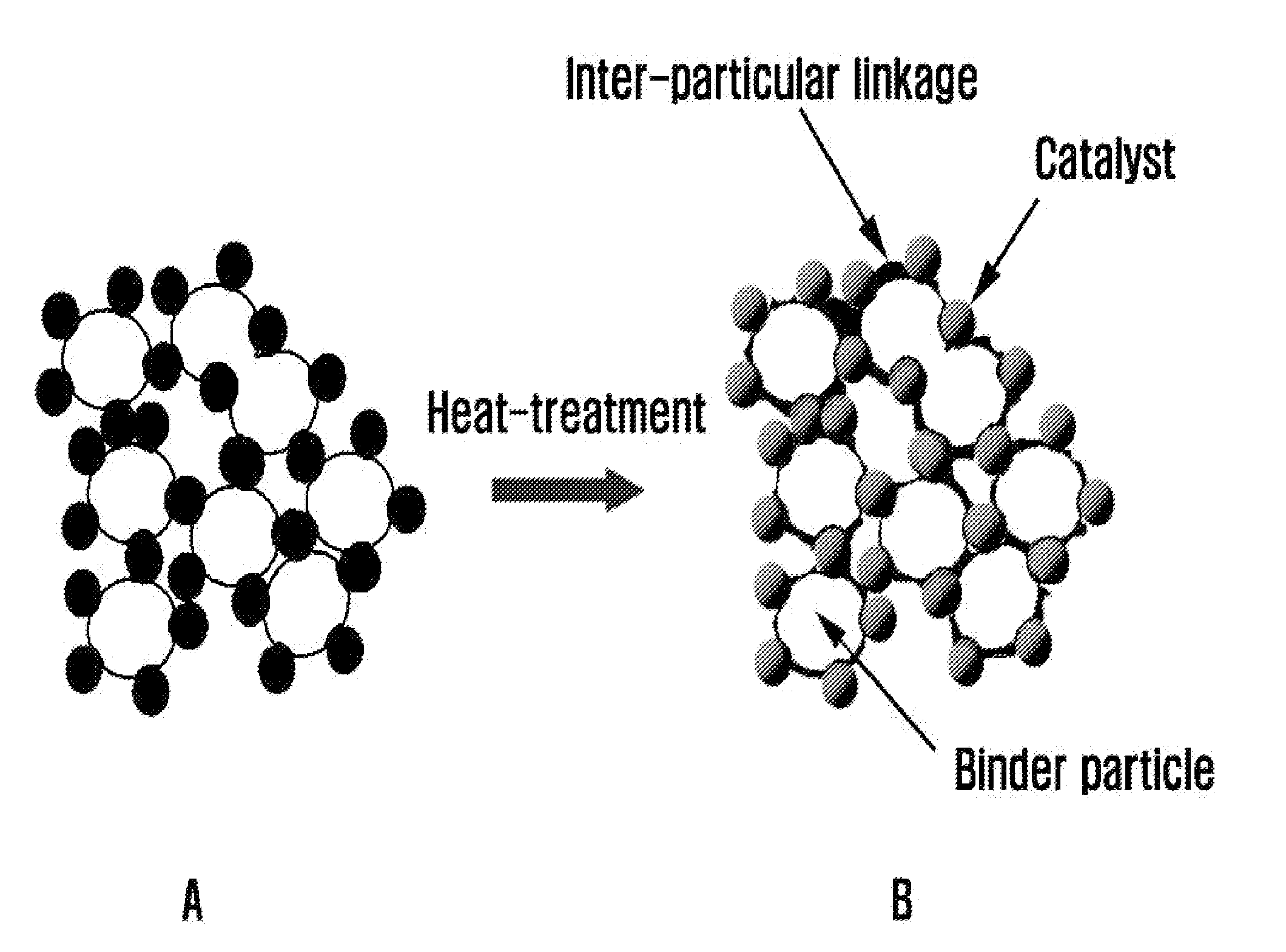
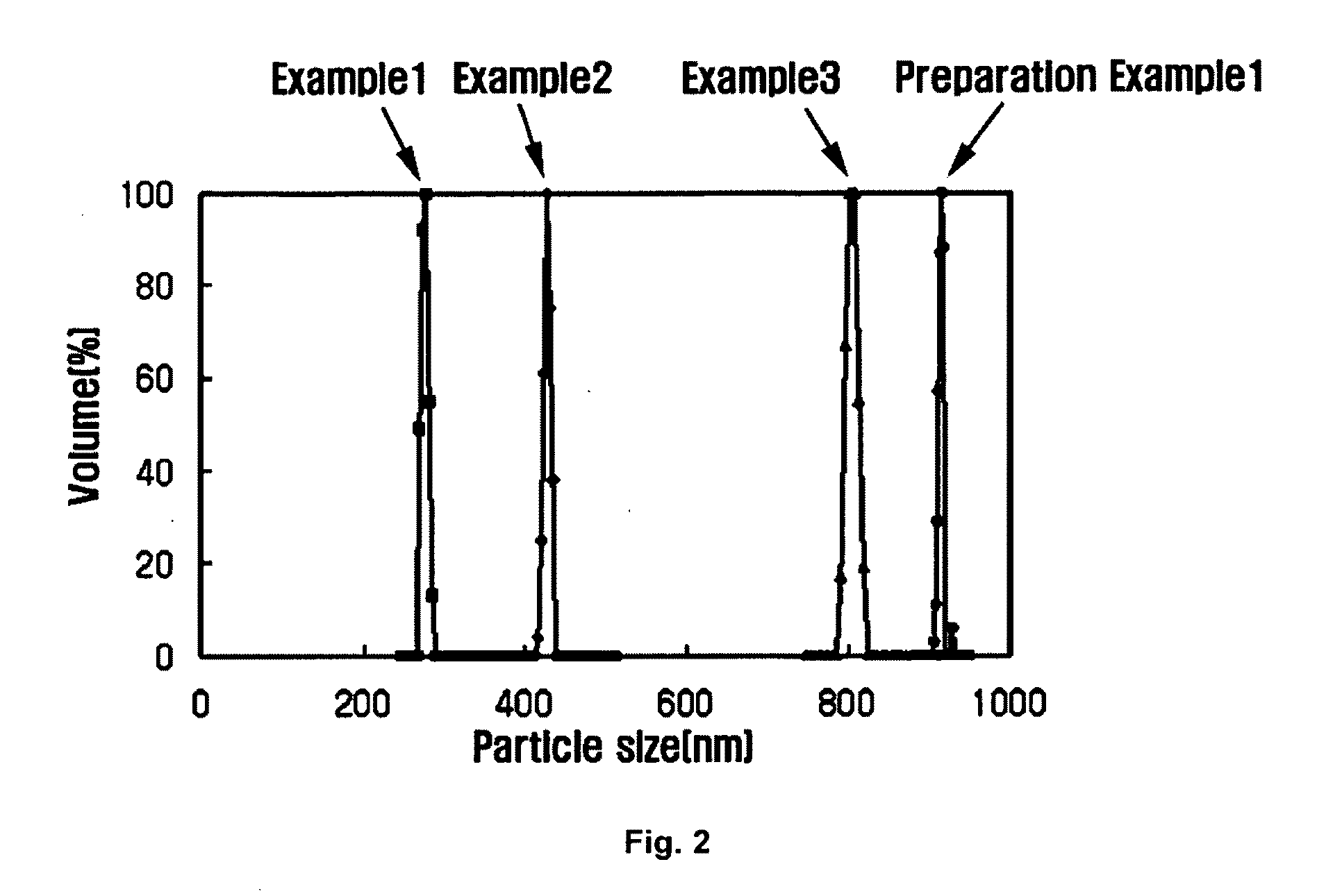
[0013]The present invention provides the advantageous effect that, by introducing a nonsolvent, cohesion of the electrode binder and the nonsolvent is induced in the electrode binder composition to form nanometer sized particles, thereby increasing electrode active surface area, and formation of a three-phase interface of catalyst, binder and fuel is maximized, thereby preventing cohesion between the polymer dissolved in the solvent and the catalyst and improving electrode activity.

Problems solved by technology

However, fossil energy resources might be depleted within years.
Further, because of ever-increasing oil price and environmental pollution caused by the use of fossil energy, interests in alternative energy source are increasing.
This approach, however, has drawbacks in that cohesion of the electrode catalytic layer occurs as the hydrocarbon-based polymer is dissolved in a polar solvent and introduced to the electrode and that the hydrocarbon-based polymer does not form particles.
Although this approach improved the interfacial stability of the membrane and electrode as the electrode binder solution comprises the same material as the proton exchange polymer electrolyte membrane, it still has a drawback in that cohesion between the catalyst and the polymer dissolved in the polar solvent occurs, decreasing the performance of the electrode and MEA.

Method used


Image

  • Electrode binder solution composition for polymer electrolyte fuel cell
  • Electrode binder solution composition for polymer electrolyte fuel cell
  • Electrode binder solution composition for polymer electrolyte fuel cell

Examples


example 1

[0044]A mixture solvent comprising 97 wt % of DMAc (solvent) and 3 wt % of acetic acid (nonsolvent) was prepared.

[0045]An electrode binder solution composition for a polymer electrolyte fuel cell was prepared using 5 wt % of the sulfonated polyetheretherketone polymer and 95 wt % of the mixture solvent prepared above.

preparation example 1

[0050]Platinum catalyst (20% Pt / C catalyst, E-Tek) was added to the binder solution composition for a polymer electrolyte fuel cell prepared in Example 1, and dried at 80° C. Then, electrode catalyst slurry was prepared by heat-treating at 150° C. for 1 hour. The prepared catalyst slurry was maintained in uniformly dispersed state by repeating ultrasonication and agitation for 24 hours, and was cast on carbon fiber at a supporting amount of 0.1 mg Pt / cm2.


PUM

PropertyMeasurementUnit
particle sizeaaaaaaaaaa
weight %aaaaaaaaaa
weight %aaaaaaaaaa

Abstract

The present invention relates to an electrode binder solution composition for a polymer electrolyte fuel cell comprising a mixture of a solvent and a nonsolvent. The electrode binder solution composition can significantly improve electrode activity by maximizing formation of a three-phase interface of catalyst, binder and fuel at the electrode catalytic layer of the polymer electrolyte fuel cell. The present invention relates to a preparation method of an electrode binder solution for a polymer electrolyte fuel cell, the electrode binder solution for a polymer electrolyte fuel cell comprising a sulfonated proton exchange hydrocarbon-based polymer and a mixture of a solvent and a nonsolvent. The present invention also relates to a preparation method of an electrode catalyst slurry comprising the steps of: mixing an electrode binder solution composition for a polymer electrolyte fuel cell with a platinum catalyst and drying the mixture; and heat-treating the dried mixture to maximize interface between the electrode binder and the catalyst.

Description

CROSS-REFERENCE TO RELATED APPLICATION[0001]This application claims under 35 U.S.C. §119(a) the benefit of Korean Patent Application No. 10-2008-0041741 filed May 6, 2008, the entire contents of which are incorporated herein by reference.[0002]1. Technical Field[0003]The present disclosure relates to an electrode binder solution composition for a polymer electrolyte fuel cell comprising a mixture of a solvent and a nonsolvent, which can significantly improve electrode activity by maximizing formation of a three-phase interface of catalyst, binder and fuel at the electrode catalytic layer of the polymer electrolyte fuel cell. The present invention relates to a preparation method of an electrode binder solution for a polymer electrolyte fuel cell, the electrode binder solution for a polymer electrolyte fuel cell comprising a sulfonated proton exchange hydrocarbon-based polymer and a mixture of a solvent and a nonsolvent. The present invention also relates to a preparation method of an...

Claims


Application Information

Patent Timeline
Patent Type & Authority Applications(United States)
IPC IPC(8): H01M8/00
CPCH01M4/8668H01M4/8828H01M4/90Y02E60/522H01M4/928H01M8/1002Y02E60/523H01M4/92H01M8/1007Y02E60/50H01M8/10C08L101/12
Inventor CHO, KI YUNPARK, JUNG KIJUNG, HO YOUNGSUNG, KYUNG A.
Owner HYUNDAI MOTOR CO LTD
Learn More