
Substrate for mounting light-emitting element, production process thereof and light-emitting device

a technology of light-emitting elements and substrates, which is applied in the direction of coatings, layered products, chemistry apparatuses and processes, etc., can solve the problems of insufficient prevention of reflectance deterioration, silver is likely to be corroded, and the reflectance (optical reflectance) tends to deteriorate, so as to prevent the cohesion of silver ions, prevent the deterioration of reflectance, and prevent the effect of silver coloring

Active Publication Date: 2015-06-09
ASAHI GLASS CO LTD
View PDF11 Cites 1 Cited by
  • Summary
  • Abstract
  • Description
  • Claims
  • Application Information

AI Technical Summary

Benefits of technology

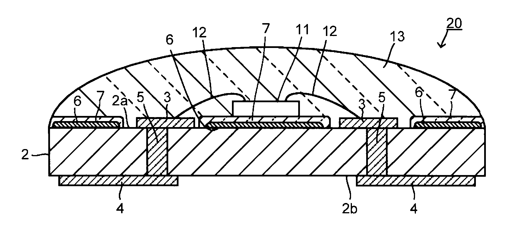
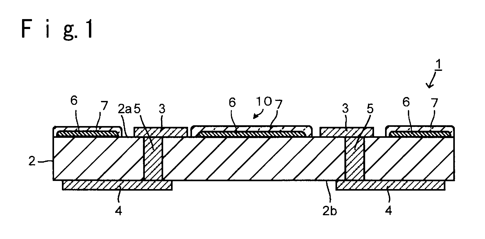
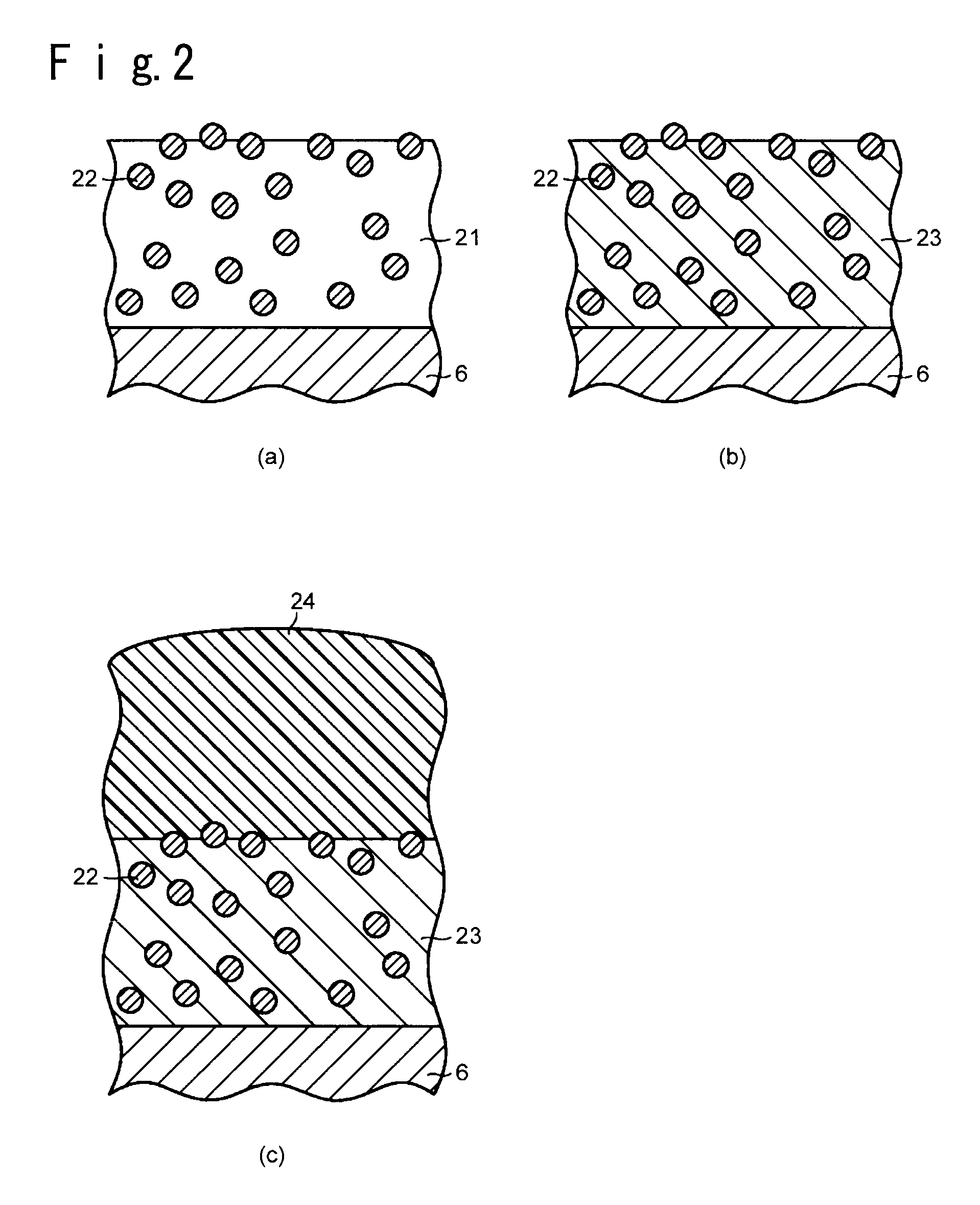
[0021]According to the substrate for mounting a light-emitting element of the present invention, by providing a protective layer containing a glass having silver ions diffused therein so as to cover the entire surface of the silver reflection layer, it is possible to prevent cohesion of silver ions and formation into colloidal particles on the surface of the protective layer and thereby to prevent silver coloring, whereby it is possible to prevent deterioration of reflectance. Further, since an alumina filler is contained in the protective layer, it is possible to obtain a substrate for mounting a light-emitting element having a low heat resistance and improved flatness of a mounting portion of a light-emitting element. Further, it is possible to form the silver reflection layer on the substrate and the protective layer formed on the silver reflection layer by firing them simultaneously, and therefore burden on the step can be suppressed.
[0022]In the light-emitting device of the present invention, the above-described substrate for mounting a light-emitting element is used, whereby the reflectance of the reflection layer tends to hardly deteriorate, and it is possible to maintain the luminous efficiency for a long period of time. Further, inclination or damage of the light-emitting element can be suppressed, and therefore it is possible to obtain favorable emission light which is free from fluctuation in light distribution characteristics.

Problems solved by technology

However, silver is likely to be corroded, and if it is left to stand in an exposed state, oxidation or sulfurization tends to occur on the surface of the silver reflection layer, whereby reflectance (optical reflectance) tends to deteriorate.
However, by such a method, moisture or a corrosive gas is likely to pass through the resin or enter from the interface between the silver reflection layer and the resin, whereby it was impossible to sufficiently prevent the deterioration of the reflectance due to corrosion (oxidation or sulfurization) of the silver reflection layer.
However, in such a case where a glass layer is provided as a protective layer, deformation due to e.g. swell tends to occur during firing since a glass usually has a high fluidity in a non-fired state, whereby the flatness of the surface of a glass layer deteriorates.
Further, if irregularities are formed on the mounting portion, the light-emitting element is likely to be fixed with an inclination and damaged by subsequent wire bonding, and further an optical axis is also likely to be displaced.
As a result, reflectance was likely to deteriorate, whereby light intensity (brightness) as a light emitting device was likely to deteriorate.

Method used


Image

  • Substrate for mounting light-emitting element, production process thereof and light-emitting device
  • Substrate for mounting light-emitting element, production process thereof and light-emitting device
  • Substrate for mounting light-emitting element, production process thereof and light-emitting device

Examples


examples

[0080]Now, the present invention will be described in further detail with reference to Examples.

examples 1 to 12

Comparative Example

[0081]Firstly, a glass ceramics composition for the protective layer was prepared. That is, glass raw materials were blended and mixed so that the respective components of SiO2, B2O3, Al2O3, CaO, Na2O and K2O would be a composition (mol %) shown in Table 1, and this raw material mixture was put into a platinum crucible and melted at a temperature of from 1,500 to 1,600° C. for 60 minutes, and then this molten state glass was cast and cooled. A glass thus obtained was ground by a ball mill made of alumina for from 20 to 60 hours to obtain a glass powder. Here, ethyl alcohol was used as the solvent for grinding.

[0082]The average particles size D50 (μm) of the glass powder for a protective layer thus obtained was measured by a particle size distribution analyzer of a laser diffraction scattering method (tradename: SALD2100, manufactured by Shimadzu Corporation). The average particle size (D50) of the glass powder having each composition, was within a range of from 1 ...


PUM

PropertyMeasurementUnit
thicknessaaaaaaaaaa
thicknessaaaaaaaaaa
thicknessaaaaaaaaaa

Abstract

To provide a substrate for mounting a light-emitting device, which is provided with a silver reflection layer having a high reflectance and being less susceptible to deterioration of the reflectance due to corrosion and which has an improved light extraction efficiency.A substrate for mounting a light-emitting element 1, which comprises a substrate main body 2, a silver reflection layer 6 composed mainly of silver or a silver alloy, formed on the substrate main body 2, and a protective layer formed so as to cover the entire surface of the silver reflection layer 6, wherein the protective layer 7 contains an alumina filler and further contains a glass constituting the protective layer 7, having silver ions diffused therein. The concentration of silver ions contained in the glass of the protective layer 7 is at least 0.5 mass % and at most 5.0 mass %.

Description

TECHNICAL FIELD[0001]The present invention relates to a substrate for mounting a light-emitting element, a production process thereof and a light-emitting device, particularly to a substrate for mounting a light-emitting element which can prevent deterioration of light extraction efficiency, a process for producing the substrate for mounting a light-emitting element, and a light-emitting device employing the substrate for mounting a light-emitting element.BACKGROUND ART[0002]In recent years, along with a tendency to high brightness and whitening of a light-emitting element such as a light-emitting diode (LED), a light-emitting device employing a light-emitting element has been used for illumination, backlights of various displays or large-sized liquid crystal TVs, etc. The substrate for mounting a light-emitting element, to mount a light-emitting element, is usually required to have a high reflectivity to efficiently reflect light emitted from the element.[0003]Accordingly, it has b...

Claims


Application Information

Patent Timeline
Patent Type & Authority Patents(United States)
IPC IPC(8): H01L33/00H01L33/60H01L33/48H01L33/64
CPCH01L33/60H01L33/486H01L33/641H01L2224/48091H01L2224/48227H01L2924/00014H01L2924/181H01L2924/00012H01L33/48
Inventor OHTA, SEIGO
Owner ASAHI GLASS CO LTD
Learn More