Synchronization system and method for changing a gear

A synchronizer and synchronizing ring technology, applied in clutches, components with teeth, mechanical drive clutches, etc., can solve problems such as increased force consumption, and achieve the effect of improving synchronizing ability

Active Publication Date: 2016-05-04
HOERBIGER ANTRIEBSTECHN HLDG
View PDF7 Cites 8 Cited by
  • Summary
  • Abstract
  • Description
  • Claims
  • Application Information

AI Technical Summary

Problems solved by technology

The disadvantage here is that an increased force consumption is required when the gear is inserted in order to overcome the frictional force generated by the synchronizer ring by means of the pressure piece

Method used


Image

  • Synchronization system and method for changing a gear
  • Synchronization system and method for changing a gear
  • Synchronization system and method for changing a gear

Examples


Embodiment Construction

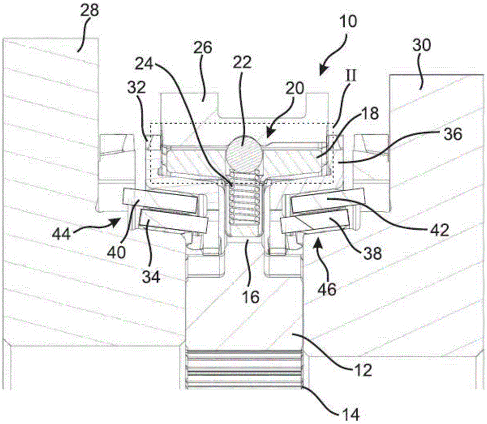
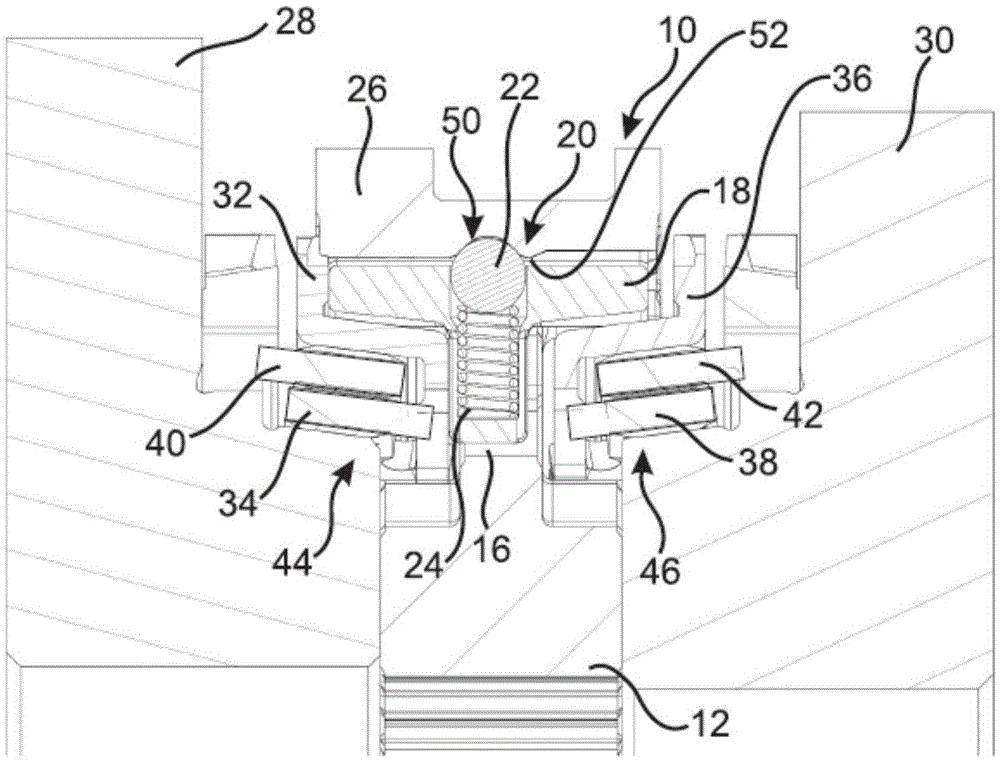
[0033] figure 1 A synchronizer 10 is shown which has a synchronizer body 12 which is arranged in a rotationally fixed manner via a toothing 14 on a drive shaft (not shown here). The drive shaft rotates about an axis that is at figure 1 The center is located horizontally within the toothing 14 .

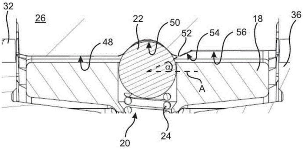
[0034] The synchronizer body 12 has a hub portion 16 in which a pressure piece 18 is adjustably arranged. The pressure piece 18 is associated with an adjustment piece 20 which, in the embodiment shown, is formed by a ball 22 and a spring 24 . Here, the spring 24 is supported on the pressure piece 18 and presses the ball 22 in the direction of the sliding sleeve 26 , ie radially outward.

[0035] The sliding sleeve 26 is connected to the synchronizer body 12 in a rotationally fixed manner, and can slide axially in opposite directions, thereby coupling the synchronizer body 12 with the first transmission gear 28 or the second transmission gear 30, whereby the torque can be transferre...


PUM


Abstract

The invention provides a synchronization system and method for changing a gear. The invention relates to a synchronization system (10) for a change-speed gearbox comprising a synchronizing body (12) which is assigned to a gearbox shaft, and comprising a first and a second synchronizing ring (32, 34, 36, 38), which are assigned to a first and a second gear wheel (28, 30) respectively. Furthermore, the synchronizing ring (10) has a sliding sleeve (26) and at least one pressure piece (18), which is displaceably arranged on the synchronizing body (12) and is able to exert an axial compressive force on the corresponding synchronizing ring (32, 34, 36, 38). Moreover, the synchronizing ring (10) has a resilient actuating element (20), which acts between the sliding sleeve (26) and the pressure piece (18), a latching recess (50) for the neutral position and a ventilation contour (54) being provided on the sliding sleeve (26). The ventilation contour (54) can interact with the actuating element (20) in such a way that, when the sliding sleeve (26) is moved in order to engage with one of the gear wheels (28, 13), the pressure piece (18) is loaded away from the corresponding synchronizing ring (32, 34, 36, 38). The ventilation contour (54) has an axial length which is no more than twice the idle stroke of the sliding sleeve (26) between the neutral position and the position in which the corresponding synchronizing ring (32, 34, 36, 38) presses against a frictional surface assigned thereto.

Description

technical field [0001] The invention relates to a synchronizer for a transmission and a method for shifting gears in a synchronizer. Background technique [0002] Synchronizers are known in the prior art which have a synchronizer body which is assigned to a transmission shaft. Typically, a pressure element is arranged in an adjustable manner on the synchronizer body, which is adjusted by the sliding sleeve during the shifting process in such a way that the synchronization ring is activated. The synchronizing ring again cooperates with the transmission gear, so that the rotational speed of the synchronizer body and the corresponding transmission gear can be synchronized. After the speed synchronization is completed, the sliding sleeve is further adjusted so that torque can be transmitted from the synchronizer body arranged on the drive shaft to the corresponding transmission gear. [0003] It is emphasized that when the sliding sleeve engages the transmission gear, the sync...

Claims


Application Information

Patent Timeline
Patent Type & Authority Applications(China)
IPC IPC(8): F16D23/06
CPCF16D2023/0618F16D2023/0631F16D23/06F16H63/30F16H2063/3093
Inventor 奥特马尔·巴克
Owner HOERBIGER ANTRIEBSTECHN HLDG
Why Eureka
Try Eureka