Magnetic recording medium including disk substrate, magnetic layer, and non-magnetic layer

a magnetic recording medium and magnetic layer technology, applied in the field of magnetic recording mediums, can solve the problems of side fringes, crosstalk, etc., improve the areal density using background-art techniques, and the sensitivity is lowered, so as to increase the frictional resistance between the magnetic head and the magnetic recording medium, the effect of increasing the frictional density and driving stably

Inactive Publication Date: 2008-10-21
TDK CORPARATION
View PDF20 Cites 8 Cited by
  • Summary
  • Abstract
  • Description
  • Claims
  • Application Information

AI Technical Summary

Benefits of technology

[0009]The present invention was developed to solve the foregoing problems. It is an object of the invention to provide a magnetic recording medium having a surface structure effective in preventing stiction between the magnetic recording medium and a magnetic head.

Problems solved by technology

However, the improved techniques adopted till now have elicited problems as to side fringes, crosstalk, etc. due to a limit of head processing and a spread of a magnetic field.
Thus, the improvement in areal density using the background-art techniques has reached its limit.
Thus, there occurs a problem that the sensitivity is lowered, the flying height of the magnetic head on the magnetic recording medium is made unstable, or foreign matters are accumulated easily.
Thus, there is a problem that a magnetic head flying on the magnetic recording medium due to an air flow in a hard disk drive or the like is stuck onto the flat surface easily, so that the magnetic head is crushed easily.
On the other hand, when the aforementioned CMP method or the like is used to flatten the surface of the magnetic recording medium, there is a problem that the magnetic head is easily stuck onto the magnetic recording medium so that the magnetic head is crushed easily.
In this state, when the surface of the magnetic recording medium is too flat, there is a problem that friction between the magnetic head and the magnetic recording medium increases so that the magnetic head is crushed easily for the same reason as mentioned above.

Method used


Image

  • Magnetic recording medium including disk substrate, magnetic layer, and non-magnetic layer
  • Magnetic recording medium including disk substrate, magnetic layer, and non-magnetic layer
  • Magnetic recording medium including disk substrate, magnetic layer, and non-magnetic layer

Examples


example 1

[0101]A non-magnetic layer 6 was formed on the to-be-processed body obtained thus. First, as a first film formation step, a film of SiO2 was formed to be 5 nm thick by a sputtering method in the conditions of 500 W in film formation power and 0.3 Pa in Ar gas pressure. Next, as a second film formation step, a film of SiO2 was formed thereon to be 45 nm thick by a sputtering method in the conditions of 500 W in film formation power, 0.3 Pa in Ar gas pressure and 150 W in bias power. Incidentally, the film thickness here means the thickness of a film on a flat surface when the film was formed on the flat surface in parallel.

[0102]Ion beam etching using Ar gas and having an incident angle of 2° was performed on the to-be-processed body for seven minutes and twenty-five seconds after the non-magnetic layer 6 was formed. Thus, a structure in which convex shapes were provided on the magnetic recording layer 5 was formed. DLC 2 nm thick was formed thereon as the protective film 7 by a CVD ...

example 2

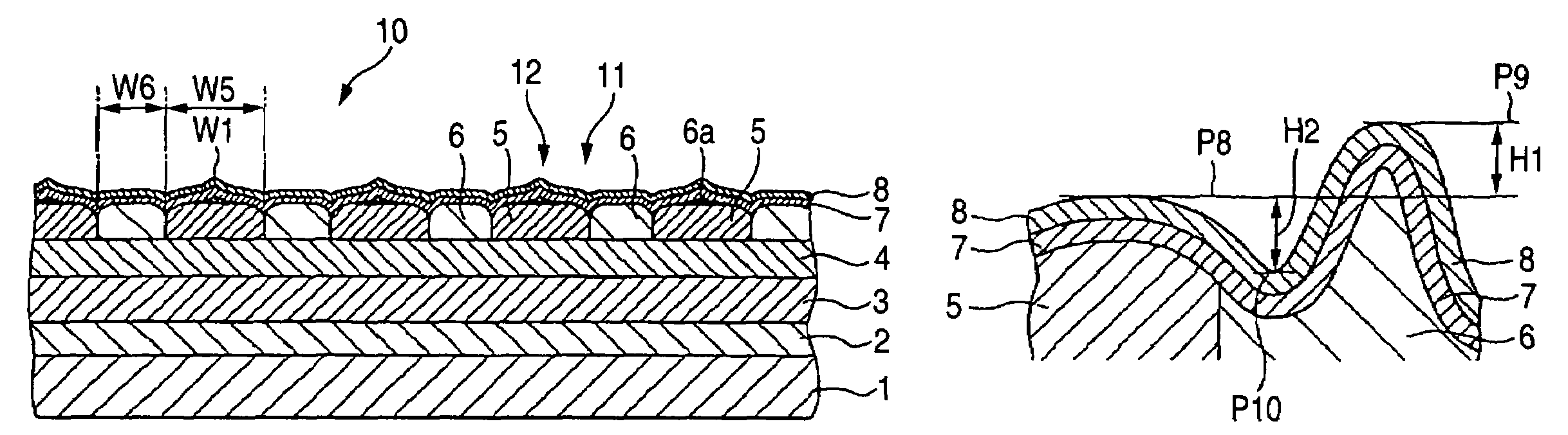
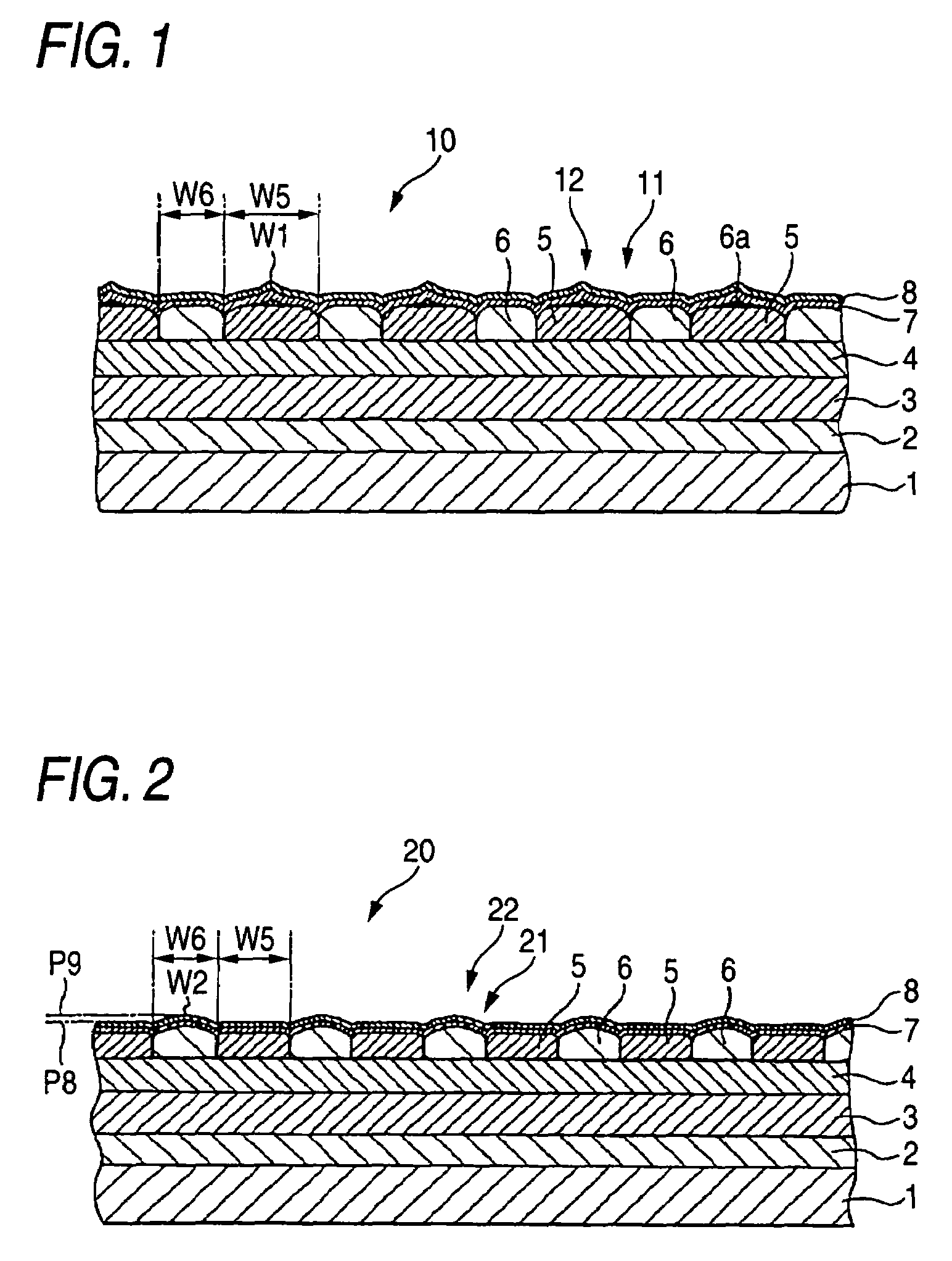
[0104]In Example 1, a non-magnetic layer 6 was formed on the to-be-processed body, and ion beam etching using Ar gas and having an incident angle of 2° was then performed on the to-be-processed body for seven minutes. After that, ion beam etching whose incident angle was changed to 90° was performed on the to-be-processed body for ten seconds. Thus, a structure in which convex shapes were provided on the magnetic recording layer 5 having the lubricating layer 8 on its outermost layer was formed. A magnetic recording medium 10 having a structure shown in FIG. 1 was manufactured in the same manner as in Example 1 except the aforementioned steps. Incidentally, the obtained magnetic recording medium had groove shapes in boundary portions between the magnetic recording layer 5 and the non-magnetic layer 6.

[0105]The magnetic recording medium 10 manufactured thus had a mode in which convex shapes 12 made of a non-magnetic material were formed on the magnetic recording layer 5 having the lu...

example 3

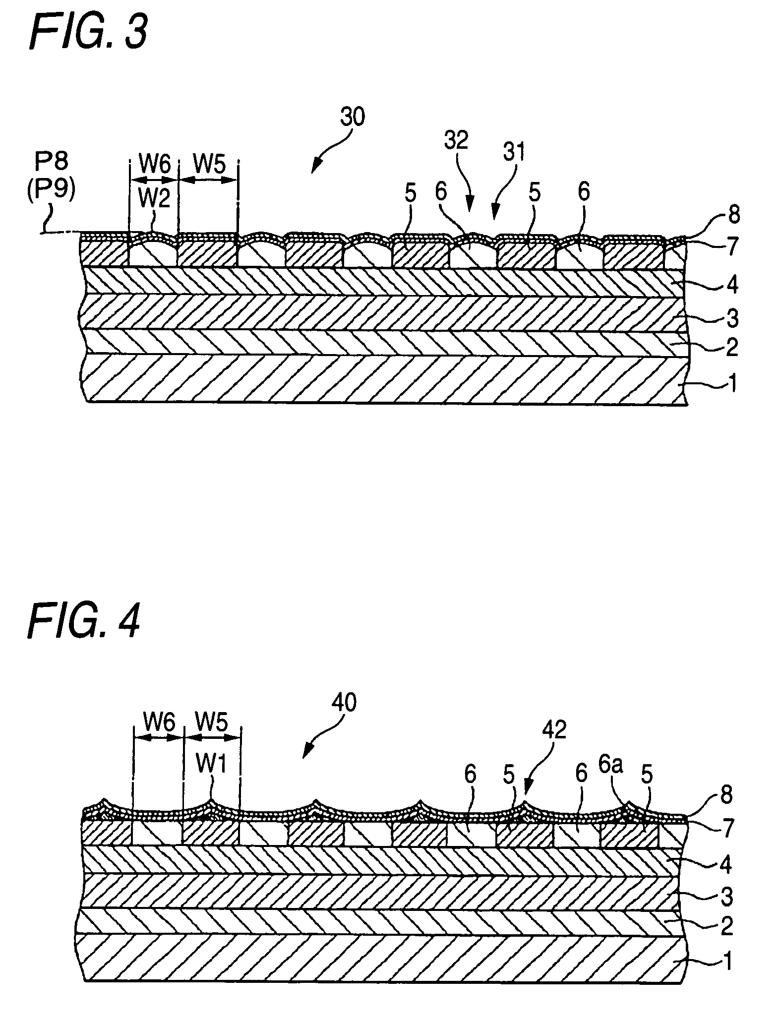
[0106]In Example 1, a non-magnetic layer 6 was formed on the to-be-processed body, and ion beam etching using Ar gas and having an incident angle of 2° was then performed on the to-be-processed body for seven minutes. After that, ion beam etching whose incident angle was changed to 90° was performed on the to-be-processed body for fifteen seconds. Thus, the non-magnetic layer on the magnetic recording layer 5 was etched so that the magnetic recording layer 5 was exposed, while a structure in which convex shapes on the non-magnetic layer 6 were formed out of the non-magnetic layer 6 was formed. A magnetic recording medium 30 having a structure shown in FIG. 3 was manufactured in the same manner as in Example 1 except the aforementioned steps. Incidentally, the obtained magnetic recording medium had groove shapes in boundary portions between the magnetic recording layer 5 and the non-magnetic layer 6.

[0107]In the magnetic recording medium 30 manufactured thus, convex shapes 32 made of...


PUM

PropertyMeasurementUnit
heightaaaaaaaaaa
heightaaaaaaaaaa
heightaaaaaaaaaa

Abstract

A magnetic recording medium includes at least a disk substrate, a magnetic recording layer formed with a predetermined concavo-convex pattern on the disk substrate, and a non-magnetic layer formed in concave portions of the concavo-convex pattern. Convex shapes made of a non-magnetic material are formed on the magnetic recording layer or the non-magnetic layer. Each convex shape is formed, for example, into a mountain-like shape whose upper surface width is made smaller than a width of each convex portion of the magnetic recording layer or a width of each concave portion where the non-magnetic layer 6 is formed.

Description

BACKGROUND OF THE INVENTION[0001]The present invention relates to a magnetic recording medium, and particularly relates to a magnetic recording medium having a surface structure effective in preventing stiction between a magnetic head and the magnetic recording medium.[0002]Magnetic recording media such as hard disks have been conspicuously improved in areal density by improved techniques such as finer granulation of magnetic particles for forming magnetic recording layers, alteration of materials, and finer head processing. Further improvement in areal density will be expected in the future. However, the improved techniques adopted till now have elicited problems as to side fringes, crosstalk, etc. due to a limit of head processing and a spread of a magnetic field. Thus, the improvement in areal density using the background-art techniques has reached its limit.[0003]As one of solutions against the problems, that is, as one of techniques, which can improve the areal density of magne...

Claims


Application Information

Patent Timeline
Patent Type & Authority Patents(United States)
IPC IPC(8): G11B5/66G11B5/72G11B5/65G11B5/82
CPCG11B5/855Y10T428/24355Y10T428/2457Y10T428/24488Y10T428/24537Y10T428/24479
Inventor SUWA, TAKAHIROTAKAI, MITSURUHATTORI, KAZUHIROOKAWA, SHUICHIHIBI, MIKIHARU
Owner TDK CORPARATION
Why Eureka
Try Eureka