Method for regulating the current through an electromagnetic actuator

a technology of electromagnetic actuators and actuators, which is applied in the direction of electric control, electric programme control, instruments, etc., can solve the problems of reducing the accuracy of control

Inactive Publication Date: 2007-04-17
ROBERT BOSCH GMBH
View PDF5 Cites 6 Cited by
  • Summary
  • Abstract
  • Description
  • Claims
  • Application Information

AI Technical Summary

Benefits of technology

[0004]An object of the present invention is to provide a method for regulating the current through an electromagnetic actuator, which permits higher accuracy of control.
[0006]The change in the time duration of an on and off switching cycle represents a change in the so-called chopper frequency of the PWM signal. Such a change in the chopper frequency makes it possible to reduce a so-called seating bounce of the electromagnetic actuator. It is likewise possible to reduce the hysteresis of the actuator, particularly in the middle current range, by decreasing the chopper frequency. The chopper frequency may be selected as a function of temperature, so that the frictional hysteresis of the actuator is reduced by a drop in the chopper frequency. All in all, the control, according to the present invention, of the current through the actuator can be substantially improved by the influencing of the time duration of the on and off switching cycle of the PWM signal.
[0007]This control is further improved by the dither function. In particular, with the aid of the low-frequency oscillation of the PWM signal, the movable iron core of the actuator is prevented from going over to a state of static friction. Thus, the iron core may be kept continually in a state of sliding friction by the dither function, resulting in minimum hysteresis of the actuator.
[0009]This brings with it the advantage that the dither function all in all has no influence on the average current which flows through the actuator.
[0014]According to the present invention, this permits a redundant check of the overall regulation of the current through the actuator. Thus, it is not only possible to compare the measured current to the setpoint value, in addition, the current ascertained from the on and off switching moments may also be compared to the measured current and / or to the setpoint value. There is therefore the possibility of being able to react better to short circuits and current variations caused by malfunctions.

Problems solved by technology

A problem with the conventional control is that the electromagnetic actuator usually has a hysteresis.
The result is that, for example, when the actuator is used for a transmission control of a motor vehicle, exact shifting operations of the transmission are no longer able to be easily carried out because of inaccuracies of the control resulting from the hysteresis.
Thus, the iron core may be kept continually in a state of sliding friction by the dither function, resulting in minimum hysteresis of the actuator.

Method used


Image

  • Method for regulating the current through an electromagnetic actuator
  • Method for regulating the current through an electromagnetic actuator
  • Method for regulating the current through an electromagnetic actuator

Examples


Embodiment Construction

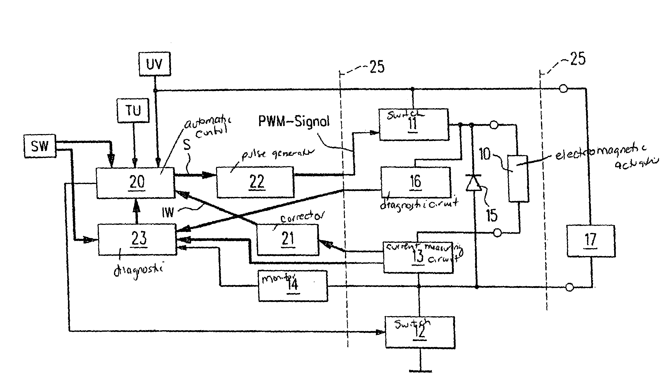
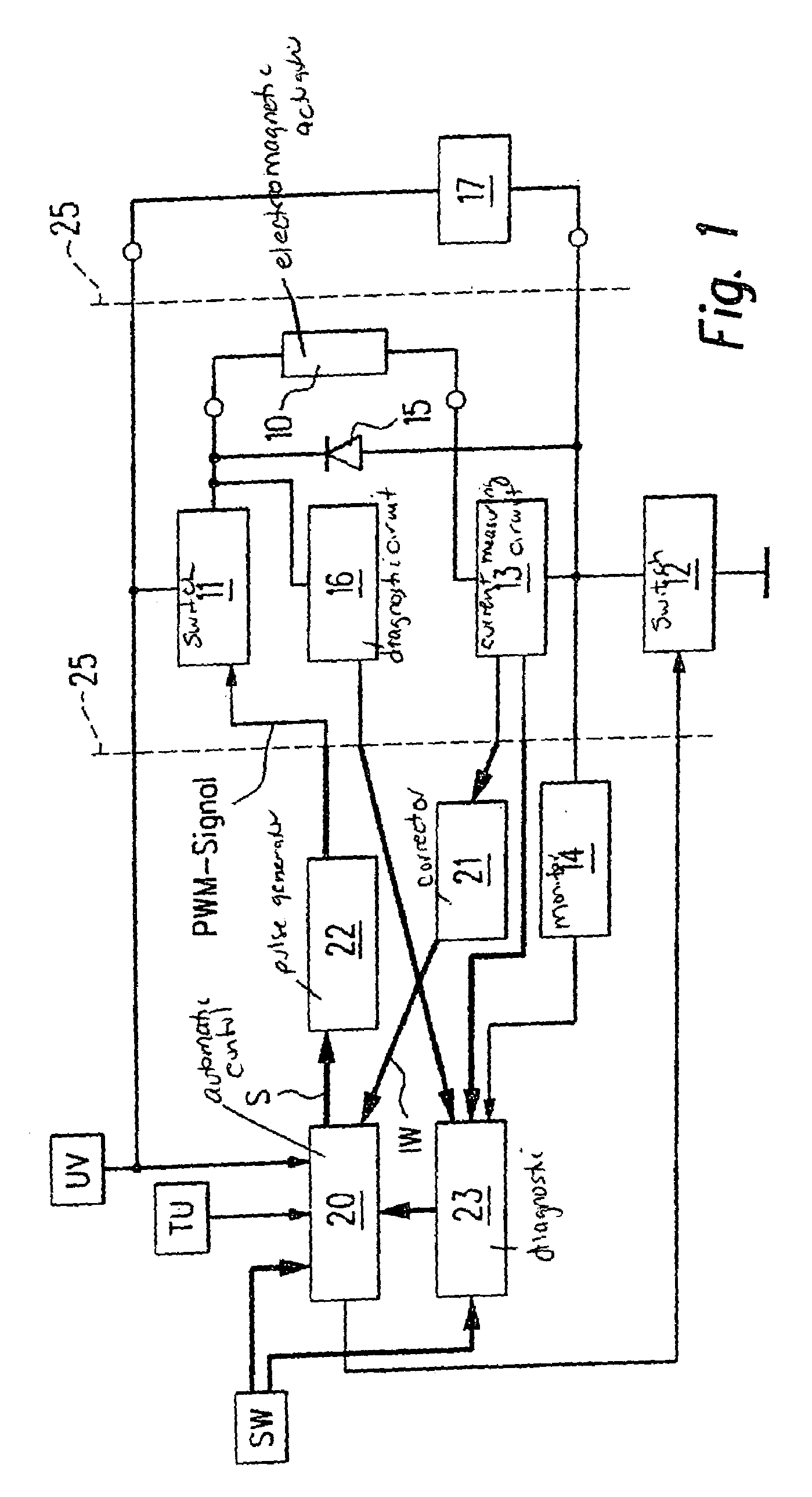
[0020]FIG. 1 shows an electromagnetic actuator 10 which, for example, may be a coil having an iron core displaceably situated therein. Actuator 10 may be used, for example, for a transmission control of a motor vehicle or as an injection valve of an internal combustion engine or the like.

[0021]Actuator 10 is connected via a first switch 11 to a supply voltage UV and via a second switch 12 to ground. A current-measuring circuit 13 is interconnected between actuator 10 and second switch 12, and a monitor 14 is connected.

[0022]A free-wheeling diode 15 is connected in parallel to actuator 10 and current-measuring circuit 13.

[0023]A diagnostic circuit 16 is connected to the connection point of actuator 10 and first switch 11. The connection point of current-measuring circuit 13 and monitor 14 is connected via a resistor 17 to supply voltage UV.

[0024]An automatic control 20 receives supply voltage UV, a signal representing ambient temperature TU and a signal characterizing a setpoint valu...


PUM


Abstract

A method for regulating the current through an electromagnetic actuator. The actuator, a first switch and a current-measuring circuit form a series circuit. A free-wheeling diode is parallel-connected to the actuator. The first switch is closed and opened by a control and a pulse generator using a PWM signal (PWM=pulse width modulation) in such a way that the current flowing through the actuator and measured by the current-measuring circuit is regulated to a setpoint value (SW). The time duration of one on and off switching cycle of the PWM signal is altered, and a so-called dither function in the form of a low-frequency oscillation is superimposed on the PWM signal.

Description

FIELD OF THE INVENTION[0001]The present invention relates to a method for regulating the current through an electromagnetic actuator, in which the actuator, a first switch and a current-measuring circuit form a series circuit, a free-wheeling diode being parallel-connected to the actuator (10), and the first switch being opened and closed by a control and a pulse generator with the aid of a PWM signal (PWM=pulse-width modulation) in such a way that the current flowing through the actuator and measured by the current-measuring circuit is regulated to a setpoint value.BACKGROUND INFORMATION[0002]A method of this kind is generally conventional. In the electrical circuit underlying the method, the PWM signal is converted with the aid of the first switch into a current across the actuator. The current flowing across the actuator is measured by the current-measuring circuit in the closed and in the open state of the first switch. The comparison to the predefined setpoint value necessary f...

Claims


Application Information

Patent Timeline
Patent Type & Authority Patents(United States)
IPC IPC(8): H01H47/00H01H47/28H01H47/32F02D41/20G05B19/19H02P25/06
CPCG05B19/19G05B2219/41156G05B2219/41206G05B2219/42235
Inventor KUEHN, WILLISTUIBLE, EWALDFACKLER, RUPERTKLEIN, CHRISTIANGUSSMANN, BERNDSCHWIENTEK, CHRISTIANMUELLER-VOGT, INGO
Owner ROBERT BOSCH GMBH
Why Eureka
Try Eureka