Communication terminal and communication system

a terminal and communication technology, applied in the field of communication systems, can solve the problems of increasing the error rate of the signal arriving at the base station, reducing the speed of downlink packet communication, and increasing the rate of the uplink data

Inactive Publication Date: 2008-04-01
MITSUBISHI ELECTRIC CORP
View PDF18 Cites 51 Cited by
  • Summary
  • Abstract
  • Description
  • Claims
  • Application Information

AI Technical Summary

Benefits of technology

[0011]According to the aforementioned structure, it is possible to improve communication quality preferentially for uplink communication by avoiding an overflow also in a case where an information signal related to downlink packet data and uplink data are simultaneously transmitted.

Problems solved by technology

If the power amplifier cannot output the power necessary for transmitting the signal, the error rate of the signal arriving at the base station increases.
Although the communication terminal transmits the information signal related to the downlink packet data, therefore, it may be impossible for the base station to correctly receive the signal, resulting in speed reduction of downlink packet communication in this case.
On the other hand, the error rate of the uplink data also increases, to result in quality deterioration of uplink communication.
Even if employing this base station, however, it is not possible to avoid an overflow caused in the communication terminal when simultaneously transmitting the information signal related to the downlink packet data and the uplink data.

Method used


Image

  • Communication terminal and communication system
  • Communication terminal and communication system
  • Communication terminal and communication system

Examples


embodiment 1

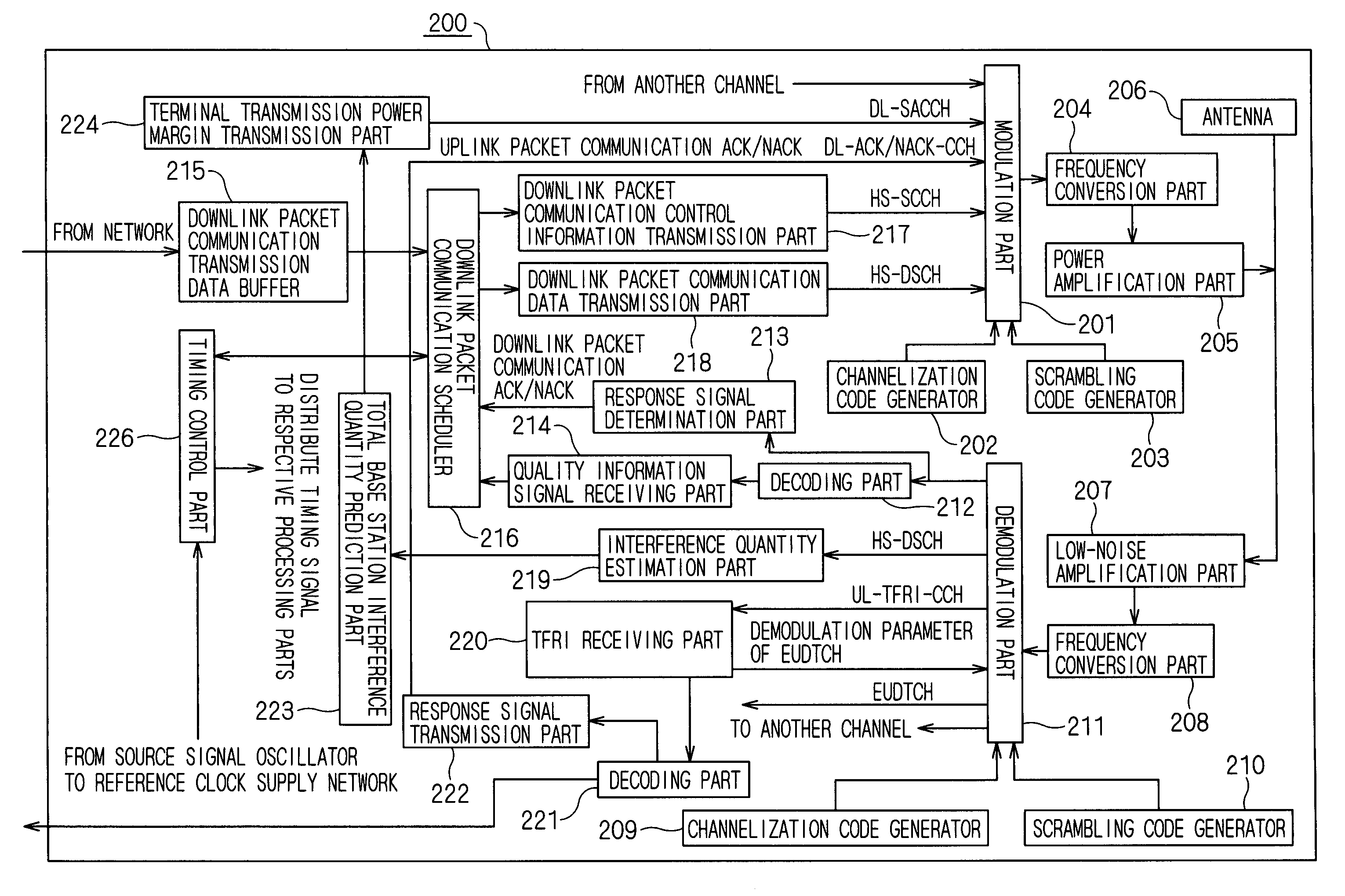
[0025]FIG. 1 is a diagram showing the structure of a packet communication system and a channel structure according to an embodiment 1 of the present invention. Description is now made with reference to the channel structure between a base station 101 and a terminal (communication terminal) 100 of the W-CDMA system. Channel names are tentative names, and may be hereafter changed. As a way of using actual channels, there is such a possibility that a doing of synergistically multiplexing a plurality of control channels on a single channel is also performed. In the W-CDMA system, the terminal 100 may be referred to as UE (User Equipment), and the base station 101 may be referred to as NodeB.

[0026]The base station 101 is controlled by an RNC (Radio Network Controller) 10 (SRNC: Serving Radio Network Controller). Information of the terminal 100 is registered in the RNC (Radio Network Controller) 10.

[0027]Downlink channels utilized for transmitting data from the base station 101 to the ter...

embodiment 3

[0139]A terminal of an embodiment 3 is characterized in transmitting a TFCI signal in selection indicating a doing of not transmitting an information signal (ACK / NACK, CQI) related to downlink packet data thereby posting that it gives priority to uplink communication to a base station, dissimilarly to the terminal of the embodiment 1.

[0140]In order to make the above post, the terminal transmits a TFCI including information indicating whether or not to use a channel employed for transmission of the information signal related to the downlink packet data to the base station, as a TFCI table shown in FIG. 11.

[0141]If the base station can receive from the terminal that it employs no HS-DPCCH, the base station can recognize that there is no transmission of an ACK / NACK or a CQI in response to the received contents. By recognizing that there is no transmission of the ACK / NACK or the CQI, retransmission of downlink packet data is prevented and a delay of downlink packet communication can be ...

embodiment 4

[0146]While the terminal according to the embodiment 1 has executed the ACK / NACK transmission stop processing (S325) shown in FIG. 8 thereby stopping transmitting the ACK / NACK or the CQI and giving priority to transmission of the uplink packet data, a terminal according to this embodiment 4 has a feature in a point of selecting a used TFCI from a TFCI table shown in FIG. 12 thereby stopping transmitting an ACK / NACK or a CQI.

[0147]Also according to such a terminal, it is possible to provide a terminal making communication giving priority to uplink communication, similarly to the embodiment 1.

[0148]In this terminal, selection of the TFCI is performed without performing the operation at the step S325 in FIG. 8. The remaining operations are similar and hence description is omitted.

[0149]In selection of the TFCI, the range allowing selection of the terminal is first decided. It is assumed here that TFC indicators #9 to #12 are limited and TFC indicators #0 to #8 are decided as the select...


PUM


Abstract

A communication system including a base station and a communication terminal transmitting / receiving data to / from this base station, in which the base station transmits downlink packet data to the communication terminal and receives an information signal related to the downlink packet data from the communication terminal that has received the downlink packet data, and the communication terminal includes an overflow estimation mechanism estimating a simultaneous transmission of uplink data and the information signal to the base station and a transmission signal control controlling transmission of the information signal in response to the result of estimation of this overflow estimation mechanism. The communication system is capable of selectively improving communication quality of either uplink communication or downlink communication by avoiding an overflow caused in a power amplification part of the communication terminal.

Description

TECHNICAL FIELD[0001]It relates to a communication system improving communication quality.PRIOR ART[0002]In such a communication system that a communication terminal receiving downlink packet data transmitted from a base station transmits an information signal related to the aforementioned downlink packet data, the transmission timing for the signal related to the downlink packet data received in the terminal and the transmission timing for uplink data may overlap with each other.[0003]In this case, the total of power necessary for transmitting the information signal related to the downlink packet data and power necessary for transmitting the uplink data may exceed the limit output value of a power amplifier of the communication terminal (hereinafter referred to as “an overflow takes place”).[0004]If the power amplifier cannot output the power necessary for transmitting the signal, the error rate of the signal arriving at the base station increases. Although the communication termin...

Claims


Application Information

Patent Timeline
Patent Type & Authority Patents(United States)
IPC IPC(8): H04B7/005H04B1/44G05D16/04G05D16/10H04J13/00H04M3/00H04W28/00H04W28/04H04W28/12H04W52/04H04W52/20H04W52/30H04W52/36H04W52/48H04W72/12H04W88/02
CPCH04W28/12H04W52/04H04W52/20H04W52/367H04W52/48H04W72/1268H04W72/1231H04W72/1242H04W72/1284H04W72/542H04W72/569H04W72/21
Inventor WAKABAYASHI, HIDEJI
Owner MITSUBISHI ELECTRIC CORP
Why Eureka
Try Eureka