Closure cap provided with anti-twisting

a technology of anti-twisting and closure cap, which is applied in the direction of engine cooling apparatus, application, refuse receptacle, etc., can solve the problems of not being able to activate and deactivate the anti-twisting and less than satisfactory

Inactive Publication Date: 2008-04-08
REUTTER HEINRICH
View PDF20 Cites 13 Cited by
  • Summary
  • Abstract
  • Description
  • Claims
  • Application Information

AI Technical Summary

Benefits of technology

[0003]The object of the present invention is to improve a pressure cap of the above kind for openings in tanks, in particular in automobile radiators, such that an anti-rotation means can be created which is directly governed by and in time and sequence with the conditions prevailing inside the tank.

Problems solved by technology

It was found that this remote arrangement of the memory spring causes problems and delays in measuring the temperature prevailing inside the tank, which leads to less than satisfactory results in activating and deactivating the anti-rotation means.

Method used


Image

  • Closure cap provided with anti-twisting
  • Closure cap provided with anti-twisting
  • Closure cap provided with anti-twisting

Examples


Embodiment Construction

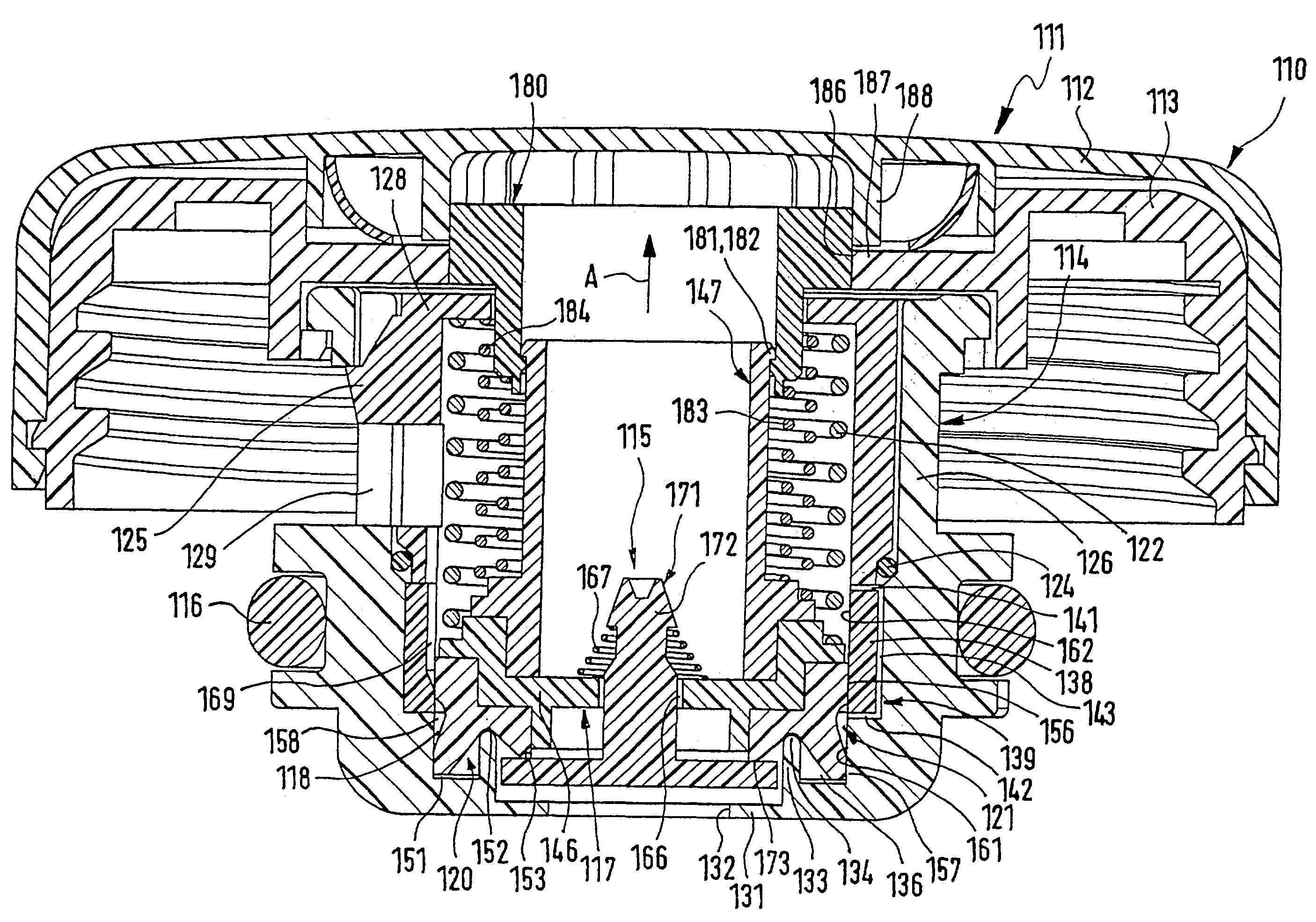
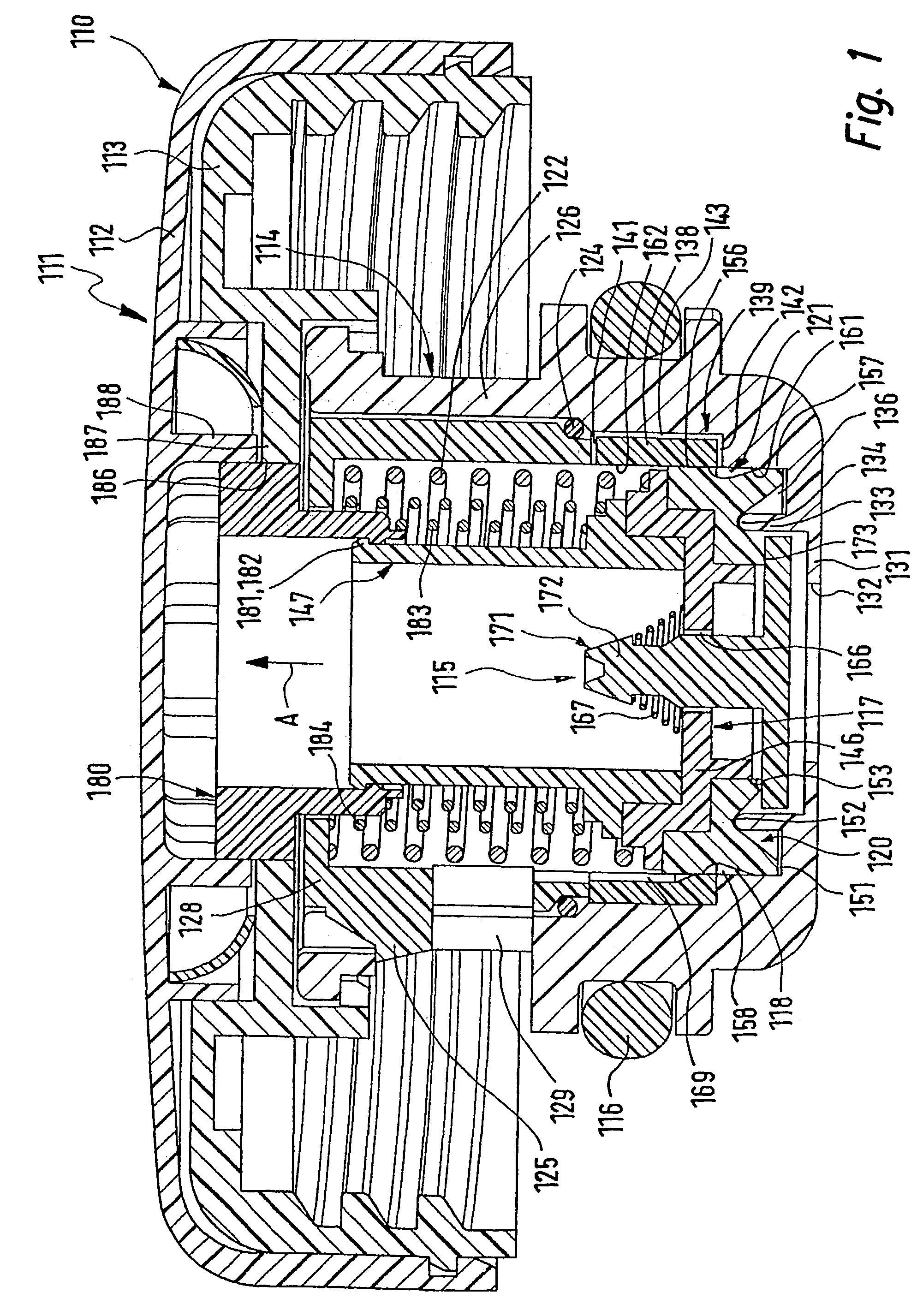
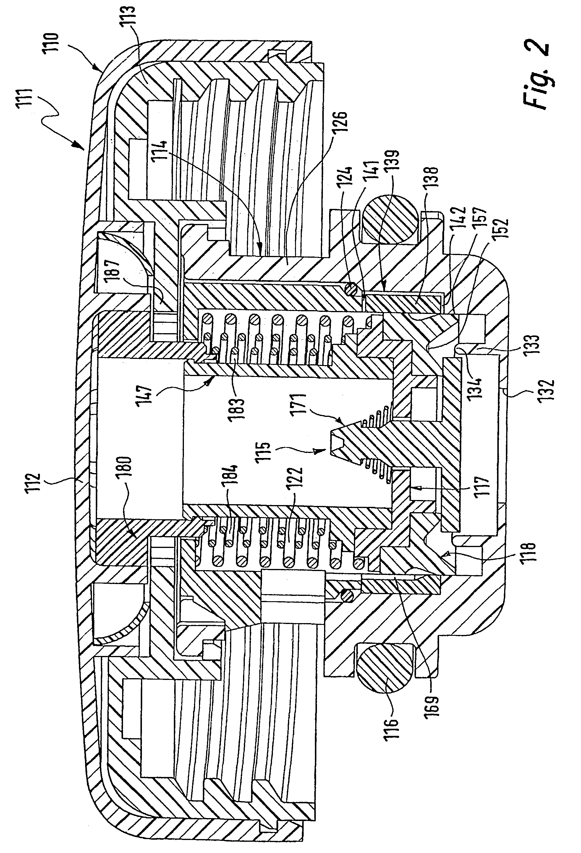
[0019]Pressure cap 111, 211 shown in the drawings by example of two embodiments for a tank such as an automobile radiator has an outer cap component 110, 210 which is provided with a handling, element or handling means 112, 212 to whose locking element 113, 213 (shown here as a screw-on element) an inner cap component 114, 214 with a pressure-relief / vacuum valve assembly 115, 215 is rotatably suspended. When in use, the pressure cap 111, 211 is fixed or screwed to a radiator neck (not shown). Inner cap component 114, 214 protrudes from the radiator neck into the inside of the radiator. An O ring 116, 216 seals the inner cap component 114, 214 against the wall of the radiator. In the two-piece outer cap component 110, 210, the cap-like handling means 112, 212 is axially fixed to the screw-on element 113, 213, although it can be rotated in circumferential direction. When there is normal pressure inside the radiator, this rotatability is blocked by an axially movable coupling insert 18...


PUM


Abstract

A pressure cap for openings in tanks, in particular in automobile radiators, has an outer cap component which is provided with a locking element that can be connected to the tank's neck, and provided with a handling element rotatably mounted in relation to said locking element, and furthermore provided with a coupling insert which is anti-rotationally mounted in the handling element and which can be axially engaged in and disengaged from the locking element to allow a releasably non-rotational connection between the locking element and the handling element. The pressure cap is furthermore provided with a valve assembly containing a valve body that can be axially moved back and forth, for releasing and blocking flow connections between the inside and the, outside of the tank depending on the pressure prevailing inside the tank. To create an anti-rotation means directly governed by and in time and sequence with the conditions prevailing inside the tank, it is provided that the engaging and disengaging movement of the coupling insert is derived from the pressure-dependent axial movement of the valve body of the valve assembly.

Description

TECHNICAL FIELD[0001]The present invention relates to a pressure cap for openings in tanks, in particular in automobile radiators, with an outer cap component which is provided with a locking element that can be connected to the tank's neck. The pressure cap is also provided with a handling element rotatably mounted in relation to the locking element, with an anti-rotation means provided with a coupling insert. The coupling insert is held non-rotatably in the handling element and can be axially moved back and forth, for the releasable anti-rotational connection of the locking element and the handling element. Included also is a valve assembly containing a valve body that can be axially moved back and forth for releasing and blocking flow connections between the inside and the outside of the tank depending on predetermined values of the pressure prevailing inside the tank.BACKGROUND OF THE INVENTION[0002]In such pressure caps for openings in tanks, in particular in automobile radiato...

Claims


Application Information

Patent Timeline
Patent Type & Authority Patents(United States)
IPC IPC(8): B65D51/16F01P11/02
CPCB60K15/0406F01P11/0247B60K2015/03547F01P11/0238F01P2011/0266Y10S220/32Y10S220/33
Inventor REUTTER, HEINRICH
Owner REUTTER HEINRICH
Why Eureka
Try Eureka