Capsule-type device and capsule-type device controlling system

a technology of capsule-type devices and controlling systems, which is applied in the field of capsule-type devices and capsule-type devices controlling systems, can solve the problems of reduced electromotive force, easy change of the attitude of capsule-type devices in the patient body, pain to the patient,

Inactive Publication Date: 2008-04-08
ASAHI KOGAKU KOGYO KK
View PDF12 Cites 263 Cited by
  • Summary
  • Abstract
  • Description
  • Claims
  • Application Information

AI Technical Summary

Benefits of technology

[0013]The present invention is advantageous in that it provides a capsule-type device and a controlling system of the capsule-type device capable of steadily generating power regardless of an attitude of the capsule type device.

Problems solved by technology

That is, the patient needs to swallow the insertion tube of the electronic endoscope, which causes pain to the patient.
One of problems of the conventional capsule-type devices described above is that there is a case where electromotive force is reduced depending on an angle formed between the coil 105 and the magnetic flux generated by the external power source because the coil 105 is formed only on the portion of the internal surface of the casing 107.
Another problem of the conventional capsule-type device is that the capsule-type device existing in the patient body easily changes its attitude (i.e., orientation), for example, by peristalsis of the digestion tube of the patient.
Therefore, it is very difficult to detect the attitude of the capsule-type device.

Method used


Image

  • Capsule-type device and capsule-type device controlling system
  • Capsule-type device and capsule-type device controlling system
  • Capsule-type device and capsule-type device controlling system

Examples


first embodiment

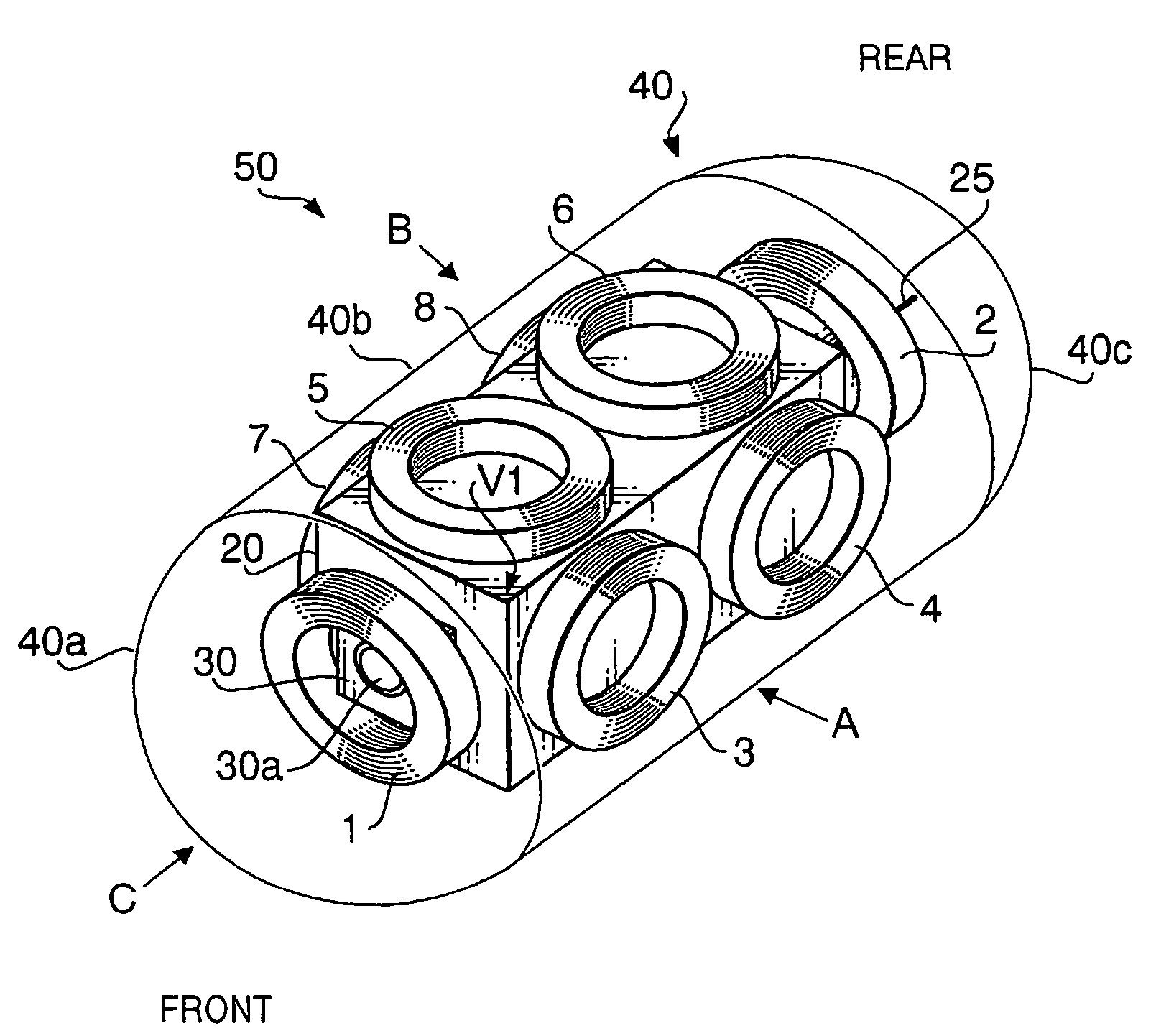
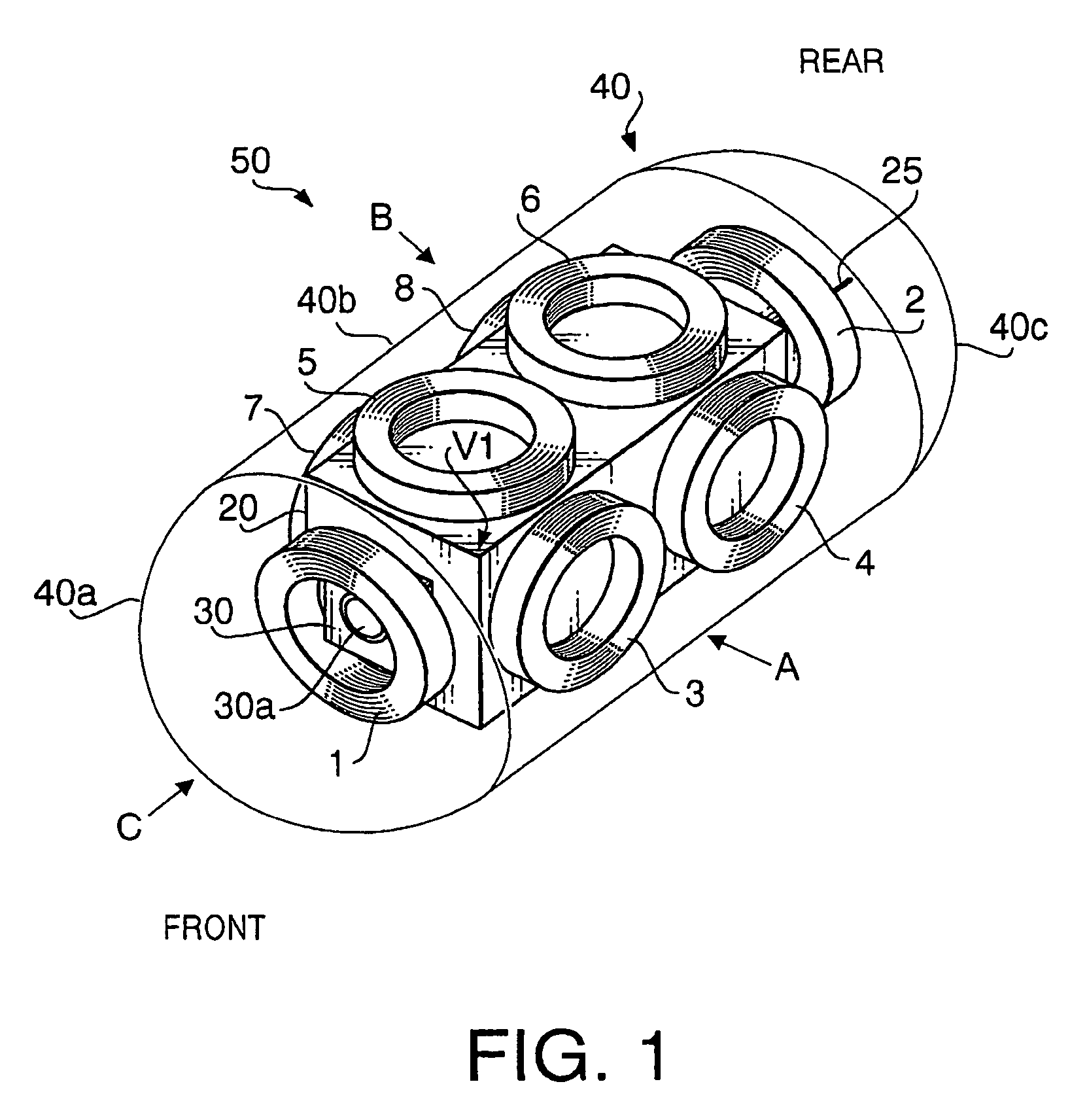
[0067]FIG. 1 is a perspective view of a capsule-type endoscope 50 according to a first embodiment of the invention. In the following explanation, the left side of the capsule-type endoscope 50 in FIG. 1 is defined as a front side, and a right side of the capsule-type endoscope 50 in FIG. 1 is defined as a rear side. The capsule-type endoscope 50 is used as a part of a capsule-type endoscope controlling system 90 (see FIG. 4).

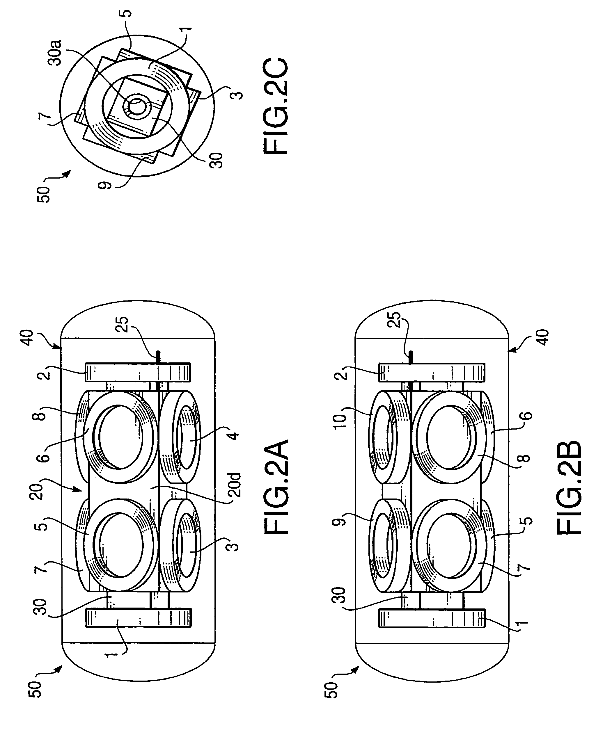
[0068]FIG. 2A is a side view of the capsule-type endoscope 50 viewed along an arrow A shown in FIG. 1. FIG. 2B is a side view of the capsule-type endoscope 50 viewed along an arrow B shown in FIG. 1. FIG. 2C is a front view of the capsule-type endoscope 50 viewed along an arrow C shown in FIG. 1. As shown in FIGS. 1 and 2A-2C, the capsule-type endoscope 50 includes an image pickup unit 30, a printed circuit board 20, and coils 1-10, which are enclosed and protected by a casing 40. The printed circuit board 20 is folded to have a form of a rectangular prism.

[0069...

second embodiment

[0112]Hereafter, a capsule-type endoscope 150 according to a second embodiment of the invention will be explained with reference to FIGS. 8-11. In FIGS. 8-11, as to elements which are similar to those of the first embodiment, the same reference numbers are assigned, and detailed explanations thereof will not be repeated. FIG. 8 is a perspective view of the capsule-type endoscope 150. Similarly to the first embodiment, the left side of the capsule-type endoscope 150 in FIG. 8 is defined as a front side, and a right side of the capsule-type endoscope 150 in FIG. 8 is defined as a rear side.

[0113]FIG. 9A is a side view of the capsule-type endoscope 150 viewed along an arrow A of FIG. 8. FIG. 9B is a side view of the capsule-type endoscope 150 viewed along an arrow B of FIG. 8. FIG. 9C is a front view of the capsule-type endoscope 150 viewed along an arrow C of FIG. 8. FIG. 10 is a developed view of a printed circuit board 120.

[0114]Similarly to the first embodiment, the capsule-type en...

third embodiment

[0122]Hereafter, a capsule-type endoscope 250 according to a third embodiment of the invention will be described with reference to FIGS. 12-14. In FIGS. 12-14, as to elements which are similar to those of the first embodiment, the same reference numbers are assigned, and detailed explanations thereof will not be repeated. FIG. 12 is a perspective view of the capsule-type endoscope 250. Similarly to the first embodiment, the left side of the capsule-type endoscope 250 in FIG. 12 is defined as a front side, and a right side of the capsule-type endoscope 250 in FIG. 12 is defined as a rear side.

[0123]FIG. 13A is a side view of the capsule-type endoscope 250 viewed along an arrow A of FIG. 12. FIG. 13B is a side view of the capsule-type endoscope 250 viewed along an arrow B of FIG. 12. FIG. 13C is a front view of the capsule-type endoscope 250 viewed along an arrow C of FIG. 12. FIG. 14 is a developed view of a printed circuit board 220. Similarly to the first and second embodiments, th...


PUM


Abstract

There is provided a capsule-type device, which is provided with a power generator that generates power by receiving at least one of a time-varying electric field and a time-varying magnetic field, and a casing that surrounds the power generator. The power generator includes a plurality of receiving elements having different directionalities with regard to the at least one of the time-varying electric field and the time-varying magnetic field.

Description

BACKGROUND OF THE INVENTION [0001]The present invention relates to a capsule-type device which is capable of generating power, for example, by receiving a time-varying magnetic field generated by an external power source. The present invention further relates to a controlling system for such a capsule-type device.[0002]Electronic endoscope systems for examining an internal body of a patient have been widely used. In general, such an electronic endoscope system includes an electronic endoscope which is inserted into the internal body of the patient, and a processor to which the electronic endoscope is attached. The electronic endoscope has an imaging device such as a CCD (charge-coupled device) at its tip portion to convert an image formed thereon by an objective lens to an image signal. The image signal is transmitted from the electronic endoscope to the processor to process the image signal. The image of a part of the internal body of the patient is thus obtained.[0003]When an endo...

Claims


Application Information

Patent Timeline
Patent Type & Authority Patents(United States)
IPC IPC(8): A61B1/04A61B1/05A61B5/06
CPCA61B1/00016A61B1/00029A61B1/041A61B5/06A61B2560/0219A61B5/062
Inventor KANAZAWA, MASAFUMI
Owner ASAHI KOGAKU KOGYO KK
Why Eureka
Try Eureka