Methods and apparatus for compensating a variable oscillator for process, voltage, and temperature variations using a replica oscillator

a technology of variable oscillator and replica oscillator, which is applied in the direction of pulse automatic control, pulse manipulation, pulse technique, etc., can solve the problems of process and voltage variation, inability to manufacture chips at slow process corners, and inability to compensate oscillator frequency output characteristics

Inactive Publication Date: 2008-04-08
SEIKO EPSON CORP
View PDF15 Cites 43 Cited by
  • Summary
  • Abstract
  • Description
  • Claims
  • Application Information

AI Technical Summary

Problems solved by technology

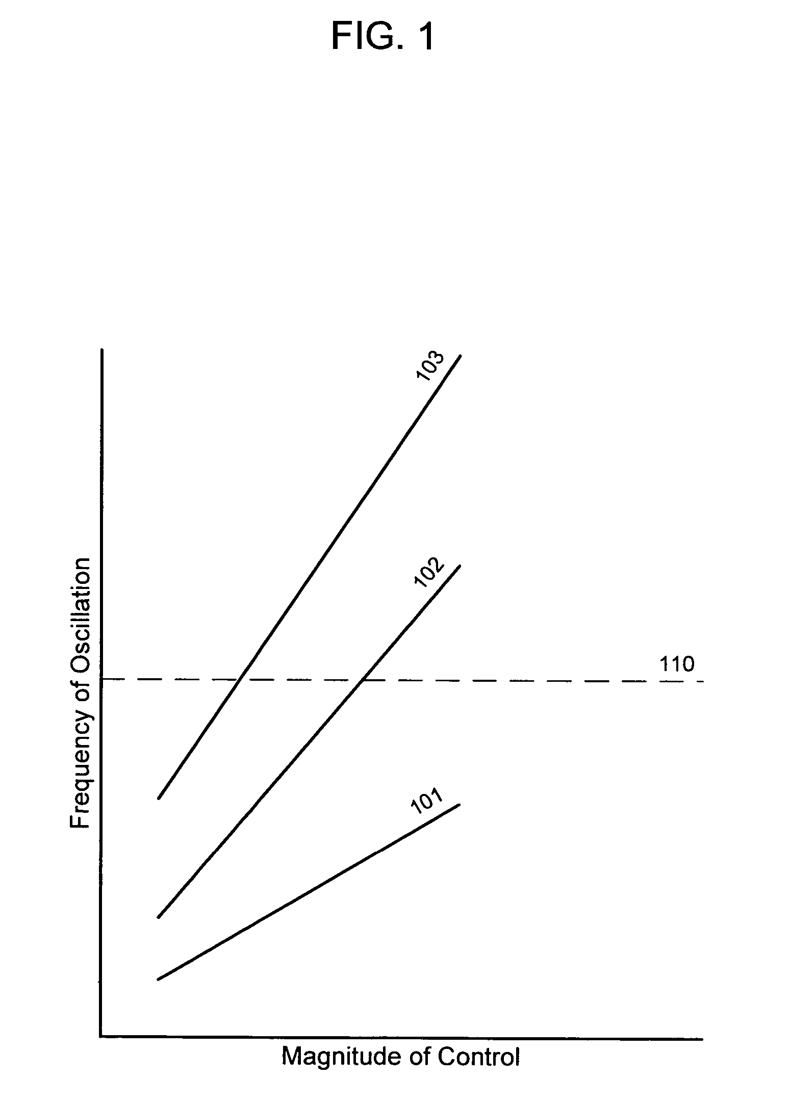
FIG. 1 shows that an oscillator may have unacceptable frequency output characteristics under some process variations.
Thus, for this hypothetical application, chips manufactured at a slow process corner generally cannot be used.
The problem of process and voltage variation particularly applies to ring oscillators.
This method generally does not measure the capacitance variation of the oscillator stages and so may not achieve full compensation for process variations.
Such analog circuitry, however, generally occupies a relatively large silicon area using conventional CMOS processes.

Method used


Image

  • Methods and apparatus for compensating a variable oscillator for process, voltage, and temperature variations using a replica oscillator
  • Methods and apparatus for compensating a variable oscillator for process, voltage, and temperature variations using a replica oscillator
  • Methods and apparatus for compensating a variable oscillator for process, voltage, and temperature variations using a replica oscillator

Examples


Embodiment Construction

[0023]Reference will now be made in detail to the preferred embodiments of the invention, examples of which are illustrated in the accompanying drawings. While the invention will be described in conjunction with the preferred embodiments, it will be understood that they are not intended to limit the invention to these embodiments. On the contrary, the invention is intended to cover alternatives, modifications and equivalents that may be included within the spirit and scope of the invention as defined by the appended claims. Furthermore, in the following detailed description of the present invention, numerous specific details are set forth in order to provide a thorough understanding of the present invention. However, it will be readily apparent to one skilled in the art that the present invention may be practiced without these specific details. In other instances, well-known methods, procedures, components, and circuits have not been described in detail so as not to unnecessarily ob...


PUM


Abstract

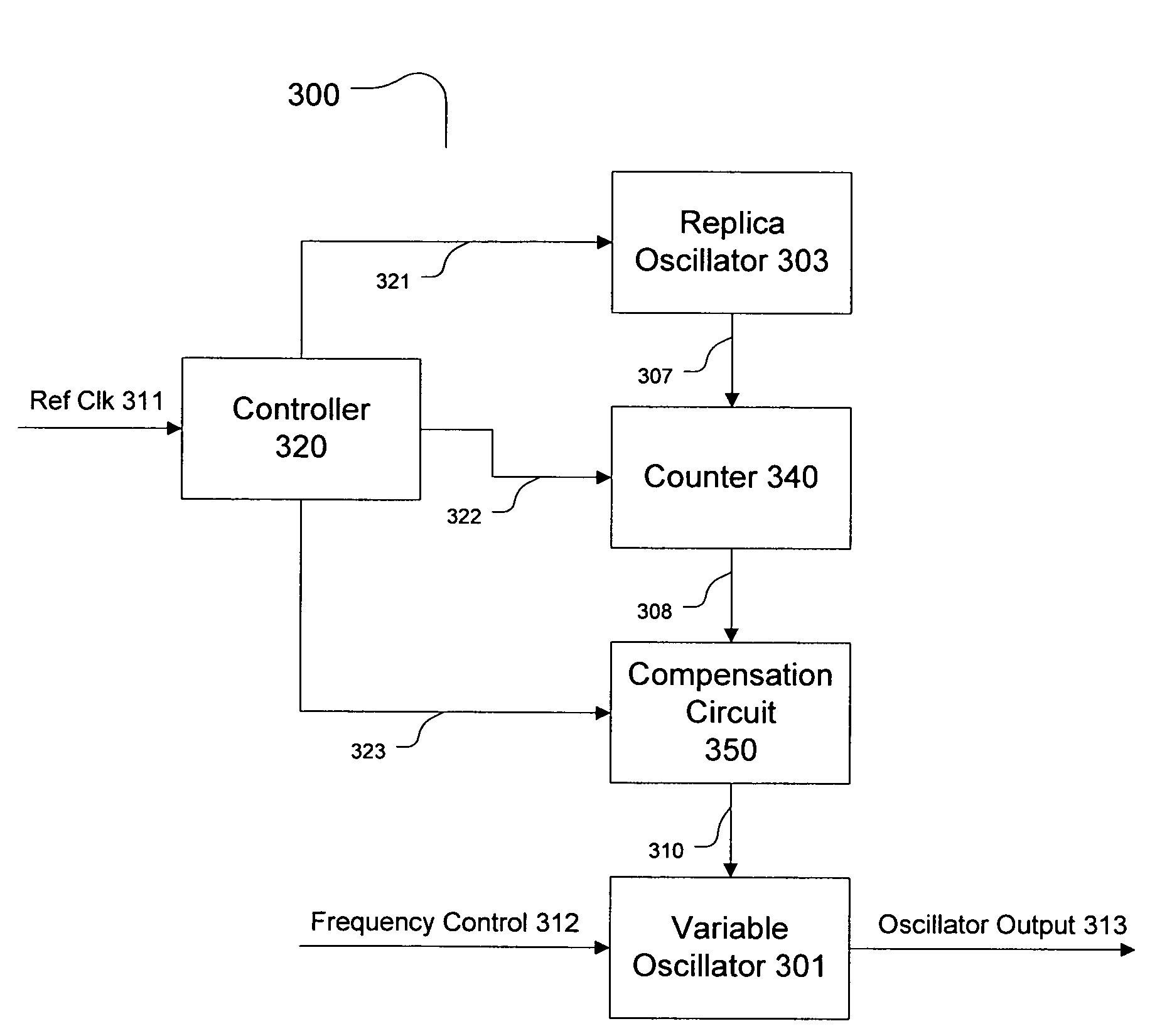
Circuits and methods for compensating a variable oscillator for process and / or operational variations. The circuit generally comprises (a) a replica oscillator, (b) a counter configured to count pulses of the replica oscillator and to produce a count signal, and (c) a compensation circuit configured to provide an adjustment signal to the variable oscillator in accordance with the count signal. The method generally comprises the steps of (a) counting the number of pulses of a replica oscillator signal, and (b) providing an adjustment signal to the variable oscillator in accordance with the number of pulses counted. The present invention advantageously provides a largely digital method to compensate a variable oscillator for process, voltage, and temperature variations.

Description

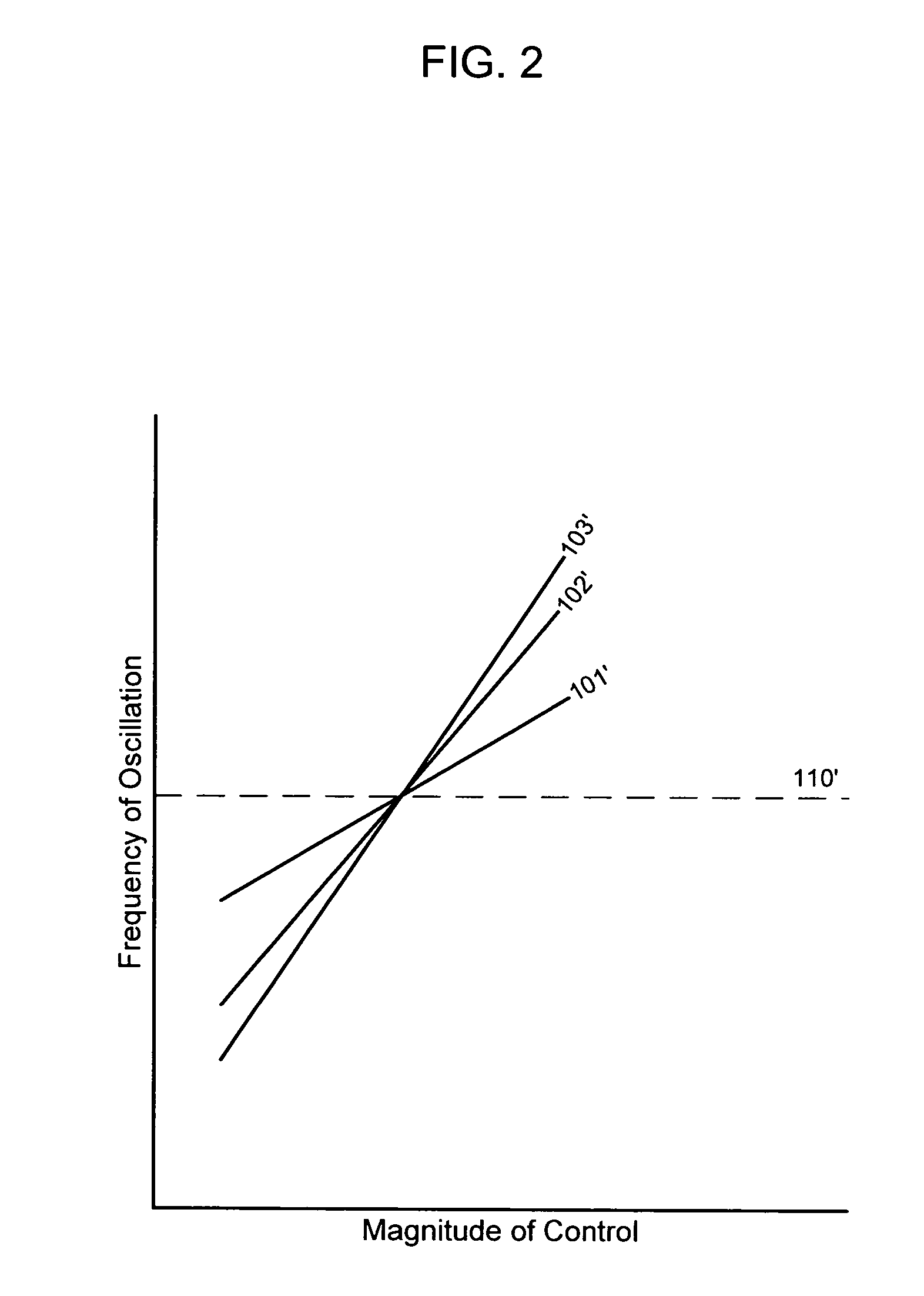
FIELD OF THE INVENTION[0001]The present invention generally relates to the field of high frequency variable oscillators, particularly to variable oscillators in phase locked loops. More specifically, embodiments of the present invention pertain to circuits and methods for maintaining a desirable oscillation frequency range in the presence of manufacturing process variations as well as variations in operating voltage and temperature.DISCUSSION OF THE BACKGROUND[0002]A variable frequency oscillator (VFO) generally produces an oscillating signal with a frequency that may be controlled by an external control. The control signal may generally comprise a variable voltage (for a voltage controlled oscillator [VCO]), a variable current, or a numeric digital value (for a digital or numerically controlled oscillator [NCO]). VFOs generally have characteristic gain curves such as those shown in FIG. 1. This gain curve relates the frequency of oscillation to the input control amplitude. FIG. 1 s...

Claims


Application Information

Patent Timeline
Patent Type & Authority Patents(United States)
IPC IPC(8): H03L7/00
CPCH03K5/133H03L7/0995H03L1/00H03K2005/00123H03K2005/0013H03K2005/00143H03L2207/06
Inventor MELTZER, DAVID
Owner SEIKO EPSON CORP
Why Eureka
Try Eureka