
Digital watermark-embedding apparatus and method, digital watermark-detecting apparatus and method, and recording medium

a digital watermark and embedded technology, applied in the field of digital watermarkembedding apparatus and method, digital watermarkdetecting apparatus and method, and recording medium, can solve the problems of poor detective precision, difficult to distinguish illegally reproduced or distributed content from corresponding original content, and difficult to detect embedded watermark data. achieve the effect of high detection precision

Inactive Publication Date: 2008-04-08
PANASONIC INTELLECTUAL PROPERTY CORP OF AMERICA
View PDF9 Cites 48 Cited by
  • Summary
  • Abstract
  • Description
  • Claims
  • Application Information

AI Technical Summary

Benefits of technology

The present invention provides a digital-watermarking art that is immune to block images and has high-detective precision. It also suppresses degradation in image quality and requires a small amount of processing. The invention uses a combination of frequency components and discrete cosine transform to achieve high-affinity for standard image-encoding. The invention also operates on variations caused by digital watermark embedment and performs calculations after selecting a region with high-level digital watermark embedment-caused variations. Overall, the invention improves the accuracy and reliability of digital watermarking.

Problems solved by technology

Therefore, it is an important issue to protect the copyright of the digital content.
Illegally reproduced or distributed content is very difficult to differentiate from corresponding original content.
This fact involves difficulties in demonstrating an evidence to assert the copyright of the content.
As a result, the embedded watermark data are difficult to detect when a block to be detected and its neighboring blocks have greatly different image complexities.
According to the process as taught by patent reference No. 1, these different images intermingled in both of the block to be detected and the neighboring blocks bring about a problem of poor detective precision.
This step may degrade image quality, depending on the complexity of a corresponding image of the determined block.
For example, when the block determined by the template is a flat image, then digital watermark embedment results in deteriorated image quality.
This means that patent reference No. 2 is improper for real-time processing.

Method used


Image

  • Digital watermark-embedding apparatus and method, digital watermark-detecting apparatus and method, and recording medium
  • Digital watermark-embedding apparatus and method, digital watermark-detecting apparatus and method, and recording medium
  • Digital watermark-embedding apparatus and method, digital watermark-detecting apparatus and method, and recording medium

Examples


first embodiment

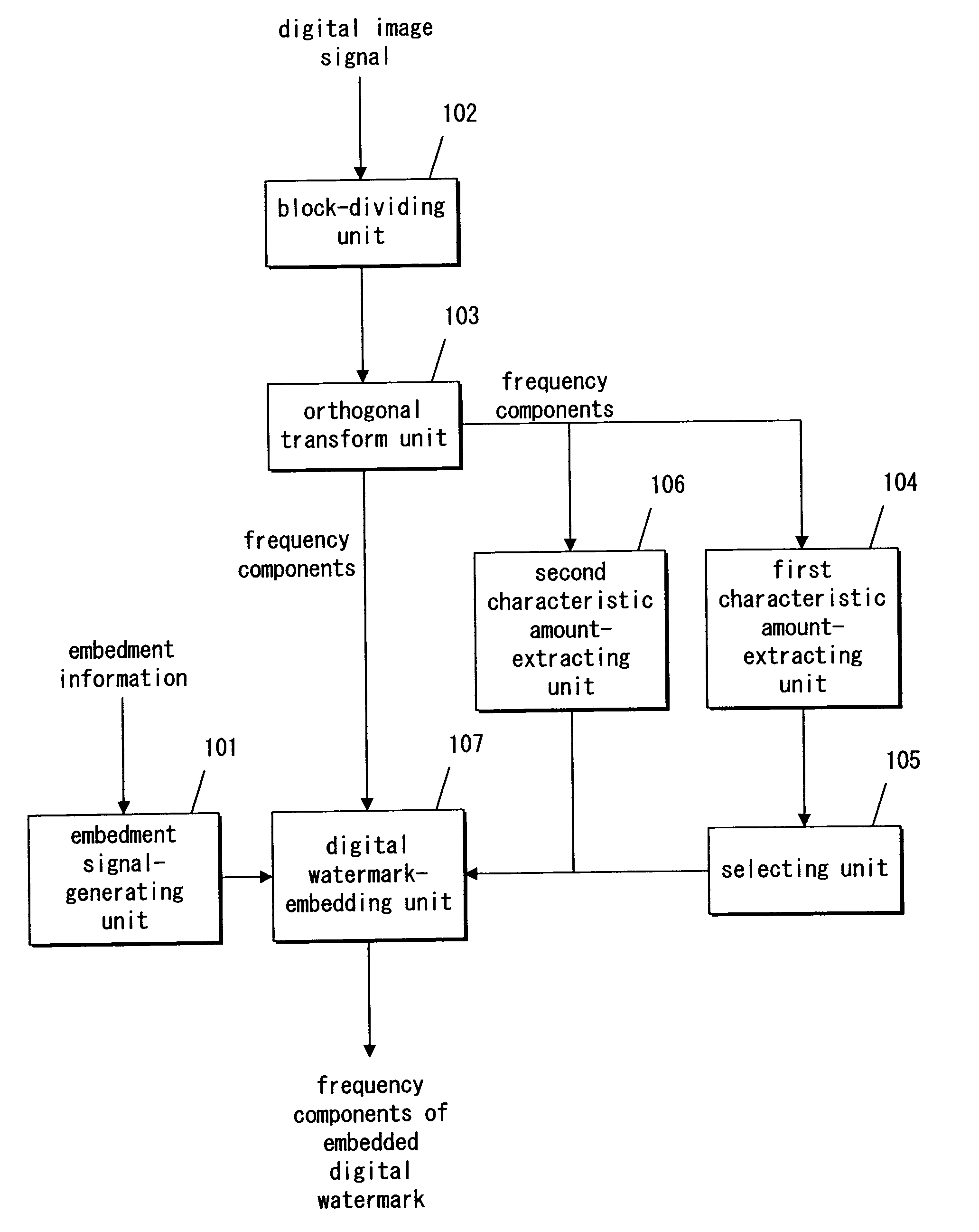
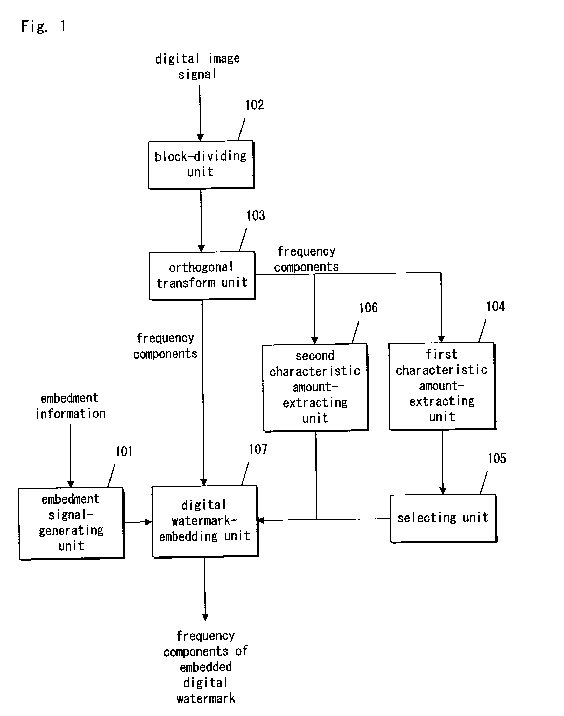
[0056]FIG. 1 is a block diagram illustrating a digital watermark-embedding apparatus according to a first embodiment.

[0057]As seen from FIG. 1, the digital watermark-embedding apparatus comprises an embedment signal-generating unit 101, a block-diving unit 102, an orthogonal transform unit 103, a first characteristic amount-extracting unit 104, a selecting unit 105, and a second characteristic amount-extracting unit 106, and a digital watermark-embedding unit 107.

[0058]The embedment signal-generating unit 101 generates, on the basis of embedment information, a signal to be embedded as a digital watermark. The block-dividing unit 102 divides a digital image signal into blocks that are formed by several pixels.

[0059]The orthogonal transform unit 103 practices the orthogonal transformation of the blocks, thereby transforming the blocks into frequency components. The digital watermark-embedding unit 107 operates a value of at least one of the frequency components under a predetermined r...

second embodiment

[0118]A second embodiment is now discussed with reference to the drawings. The present embodiment discuses a digital watermark-detecting apparatus operable to detect digital watermarks from an image signal having the digital watermarks embedded therein by the digital watermark-embedding apparatus as described in the previous embodiment.

[0119]FIG. 10 is a block diagram illustrating a structure of the digital watermark-detecting apparatus according to the present embodiment.

[0120]In FIG. 10, the digital watermark-detecting apparatus comprises an input unit 701, a block-dividing unit 702, a region-selecting unit 703, a calculating unit 704, a bit-detecting unit 705, a bit string-determining unit 706, a detected bit string output unit 707, and an adjacent region-selecting unit 708

[0121]The image signal enters the input unit 701. The block-dividing unit 702 divides the image signal from the input unit 701 into blocks that are formed by several pixels. The region-selecting unit 703 select...

third embodiment

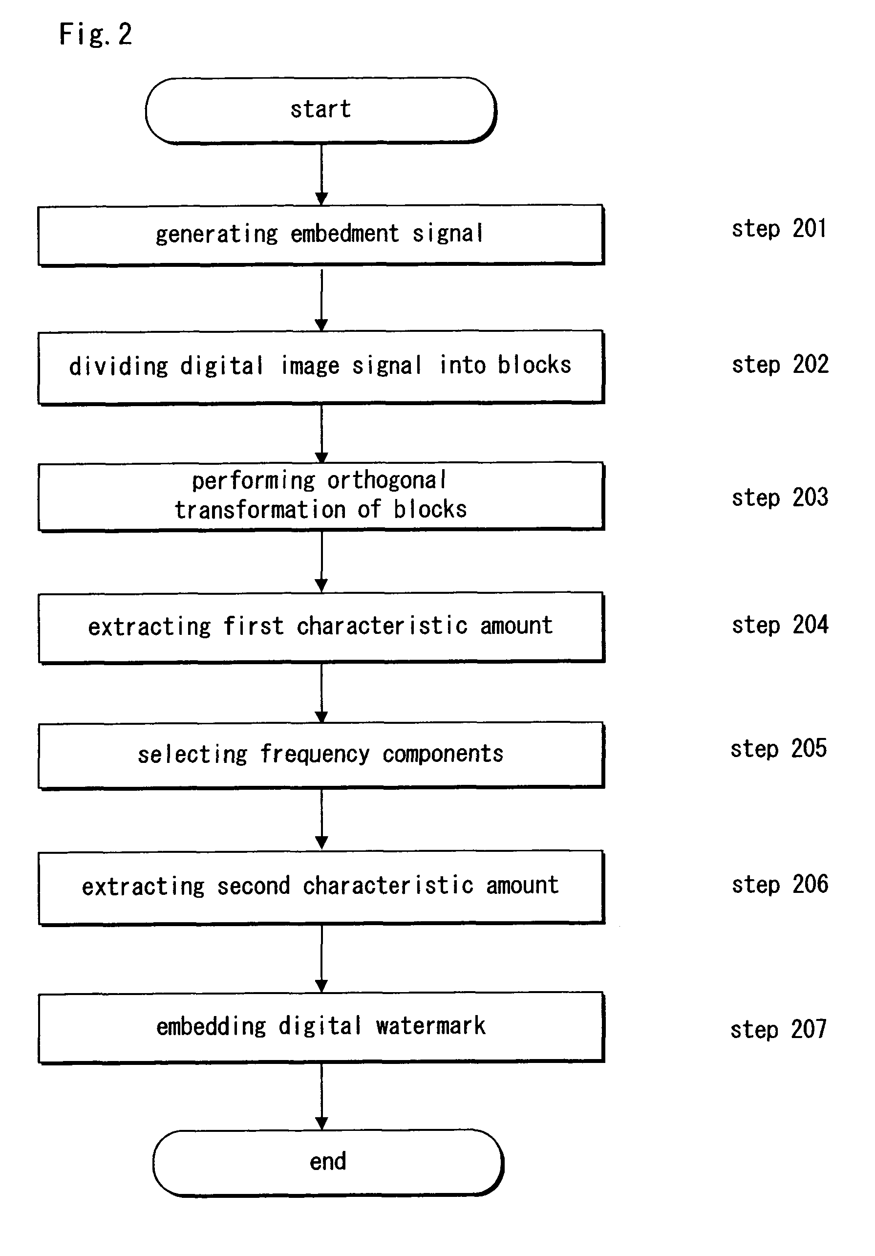
[0144]A third embodiment is now described with the drawings. A digital watermark-embedding apparatus according to the present embodiment differs in only step 201 (see FIG. 2) from that according to the first embodiment. The embedment signal-generating unit 101 (see FIG. 1) takes step 21. Therefore, the present embodiment discusses only an embedment signal-generating unit 101.

[0145]The embedment signal-generating unit 101 selects a pseudo-random number sequence that corresponds to embedment information, with reference to a reference table in which the previously prepared embedment information is related to pseudo-random number sequences. The embedment signal-generating unit 101 generates an embedment signal from the selected pseudo-random number sequence. Each bit of the generated embedment signal is allocated to one of the blocks.

[0146]The present embodiment employs a reference table having the pseudo-random number sequences related to a position and values of each bit that forms a ...


PUM


Abstract

A digital image signal is divided into blocks. Each of the divided blocks is subjected to orthogonal transformation. As a result, the divided blocks are transformed into several frequency components. One or more frequency components are selected in accordance with a characteristic amount that is extracted from the several frequency components. Values of the selected frequency components are operated under a predetermined rule in accordance with an embedment signal that is generated from embedment information.

Description

BACKGROUND OF THE INVENTION[0001]1. Field of the Invention[0002]The present invention relates to an apparatus and method for embedding embedment information as digital watermarks into an image signal, an apparatus and method for detecting the digital watermarks from the image signal, and a medium having a program recorded therein for practicing each of the above methods.[0003]2. Description of the Related Art[0004]In recent years, digital content such as digitized audio and digitized video data has been on the increase. The digital content makes it easy to provide a faithful reproduction of original content. Therefore, it is an important issue to protect the copyright of the digital content. Illegally reproduced or distributed content is very difficult to differentiate from corresponding original content. This fact involves difficulties in demonstrating an evidence to assert the copyright of the content. As a result, efforts have been made to protect the copyright of the digital con...

Claims


Application Information

Patent Timeline
Patent Type & Authority Patents(United States)
IPC IPC(8): H04L9/00G06K9/46G06T1/00
CPCG06T1/0028G06T2201/0051G06T2201/0052G06T2201/0061
Inventor NORIDOMI, KENICHIINOUE, HISASHIKATSURA, TAKASHIEJIMA, MASATAKA
Owner PANASONIC INTELLECTUAL PROPERTY CORP OF AMERICA
Learn More