Firearm support assembly

a technology for supporting assemblies and firearms, which is applied in the direction of weapons, weapon cleaning, and ammunition loading, etc., can solve the problem that the most complete of supporting assemblies cannot meet the paramount need for economic availability

Active Publication Date: 2008-04-15
KNITT CURT THOMAS
View PDF42 Cites 85 Cited by
  • Summary
  • Abstract
  • Description
  • Claims
  • Application Information

AI Technical Summary

Benefits of technology

[0044]The invention which is the subject matter hereof comprises a support framework upon which a firearm (100) may be mounted for inspection, repair, sighting and other related tasks. As with at least one of its predecessors, it comprises a maximal force-attenuated third class lever vise (61) extending upwardly from the framework (800) within which the firearm (100) stock may be secured. A rotable lag cylinder (68) is installed within the vise's movable plate (63) so as to cooperate with the vise's retraction bolt's (65) advance and withdrawal in the vise's (61) opening and closing operation.
[0045]The components in large part, are preferably constructed of relatively inexpensive tubular bar-stock (13, 14) the cut ends of which may be capped with appropriately shaped pieces (15, 16, 77).
[0046]Several points of adjustment are present. The entire

Problems solved by technology

While most of the needs and objectives have been separately met in one way or another, the assemblies m

Method used


Image

  • Firearm support assembly
  • Firearm support assembly
  • Firearm support assembly

Examples


Embodiment Construction

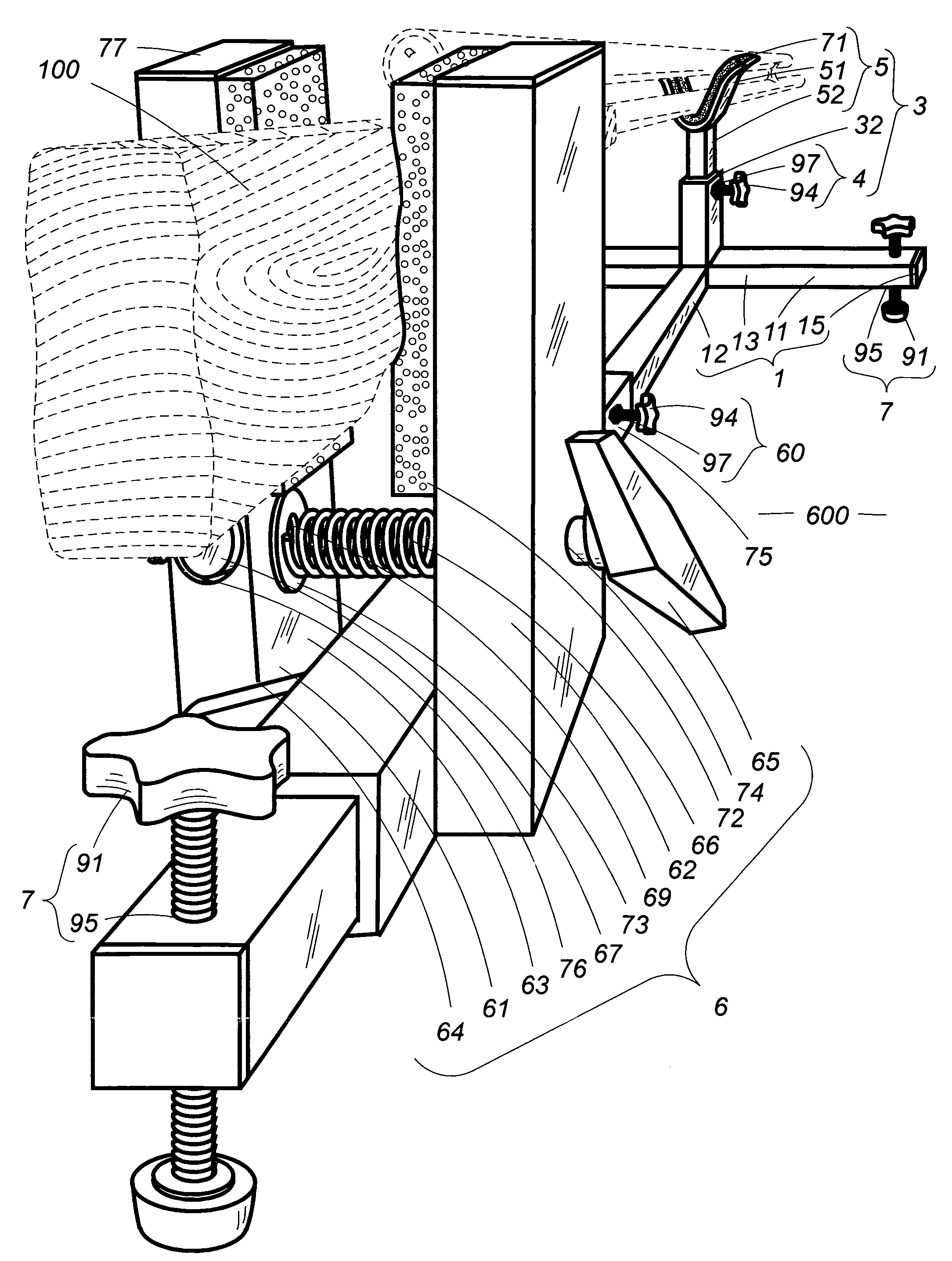
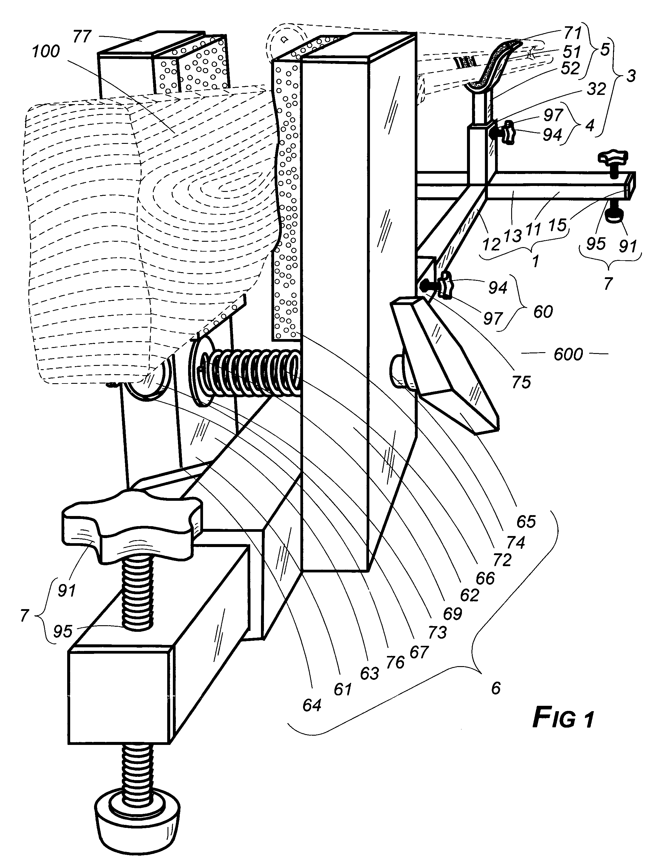
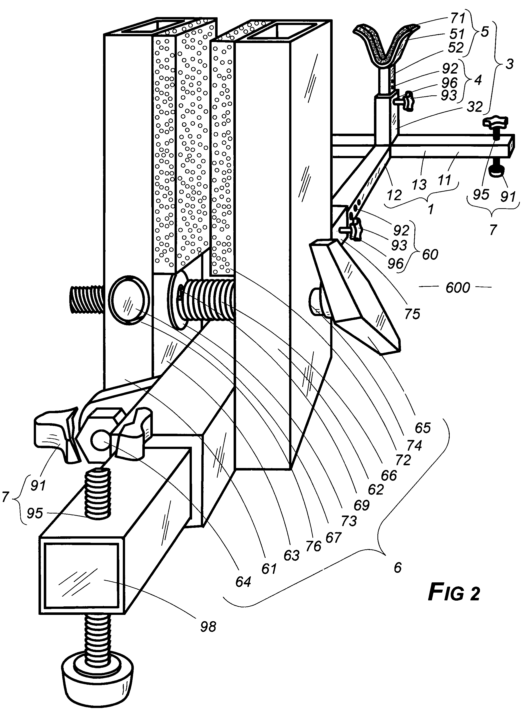
[0058]The subject of this application comprises a framework assembly upon which a firearm (100) may be emplaced for repair, scope leveling and alignment, firing and sighting adjustment or merely for display.

[0059]The framework, horizontally disposed, is in the two-dimensional sense, of generally orthogonal configuration (800), the opposing longitudinal extremities of which are herein considered for purposes of orientation as front and rear. The framework's lateral component (11) is joined to the longitudinal one (12) at the frontal sector, most preferably at the very front, these two mutually attached members (11, 12) thereby conferring upon the assembly a T-shape (1). Although solid (19) members—such as the frame (1, 800), vertical extension (31) and vice plates (62, 63)—are acceptable for the orthogonal construction (800), it (800) is preferably and more practically comprised of lighter weight and cheaper tubular bar-stock of squared (13) or rounded (14) cross-section.

[0060]An upw...


PUM


Abstract

Height and length are adjustable at several points. There is a special type of vise for holding the gunstock. As usual, the vise bolt pulls the movable plate toward the fixed one but, like some of the vise's predecessors, traces out an arc at the top, pivoting from the bottom as the bolt, situated just above the pivot, is turned. Within the movable plate a special cylinder is situated which gives and turns freely in response to the bolt's advance and withdrawal in passing through a threaded tunnel within it. This action prevents the biting down or binding upon the bolt which would otherwise occur because of the plate's pivoted travel as the bolt is advanced or withdrawn. The support's framework, best made from economical tubular bar-stock, is adjustable for leveling and leaning corrections and include anchoring blocks within the structure through which leveling bolts pass.

Description

BACKGROUND OF THE INVENTION[0001]1. Field of the Invention[0002]Firearm Accessories[0003]2. Description of the Prior Art[0004]Occasionally a descriptive term in this application may be shortened so as to recite only a part rather than the entirety thereof as a matter of convenience or to avoid needless redundancy. In instances in which that is done, applicant intends that the same meaning be afforded each manner of expression. Thus, the term cradle positioning sleeve (53) might be used in one instance but in another, if meaning is otherwise clear from context, expression might be shortened to positioning sleeve (53) or merely sleeve (53). Any of those forms is intended to convey the same meaning.[0005]The term attach or fasten or any of their forms when so used means that the juncture is of a more or less permanent nature, such as might be accomplished by nails, screws, welds or adhesives. Thus it is stated herein that the cradle's barrel rest (51) connection to the cradle neck (52)...

Claims


Application Information

Patent Timeline
IPC IPC(8): F41A27/00
CPCF41A23/16
Inventor KNITT, CURT THOMAS
Owner KNITT CURT THOMAS
Why Eureka
Try Eureka