Safety lock

a safety lock and lock body technology, applied in the field of safety locks, to achieve the effect of simplifying mechanical construction and large installation tolerances

Active Publication Date: 2008-04-15
K A SCHMERSAL
View PDF18 Cites 15 Cited by
  • Summary
  • Abstract
  • Description
  • Claims
  • Application Information

AI Technical Summary

Benefits of technology

[0007]It is an object of the invention is to provide a safety lock which permits large installation tolerances. It is a further object of the invention to provide a safety lock which allows the closing-off device to consolidate. Still a further object of the invention is to provide a safety lock having a simplified mechanical construction.
[0014]Since a catch which can be pivoted about an axis extending parallel to the movement direction of the actuator is provided, the engagement surfaces of the catch and of the actuator running perpendicularly to the movement direction, it is possible to arrange the actuator, or a housing accommodating the same, with very large installation tolerances in relation to the locking unit and to accept corresponding consolidating of the closing-off device. The tolerance may thus be, for example, 50% of the width of the actuator or more. At the same time, it is possible to simplify the mechanical design for actuating the catch.

Problems solved by technology

This design involves relatively high outlay and only allows small tolerances between the installation of the actuator and the housing of the locking unit.

Method used


Image

  • Safety lock
  • Safety lock
  • Safety lock

Examples


Embodiment Construction

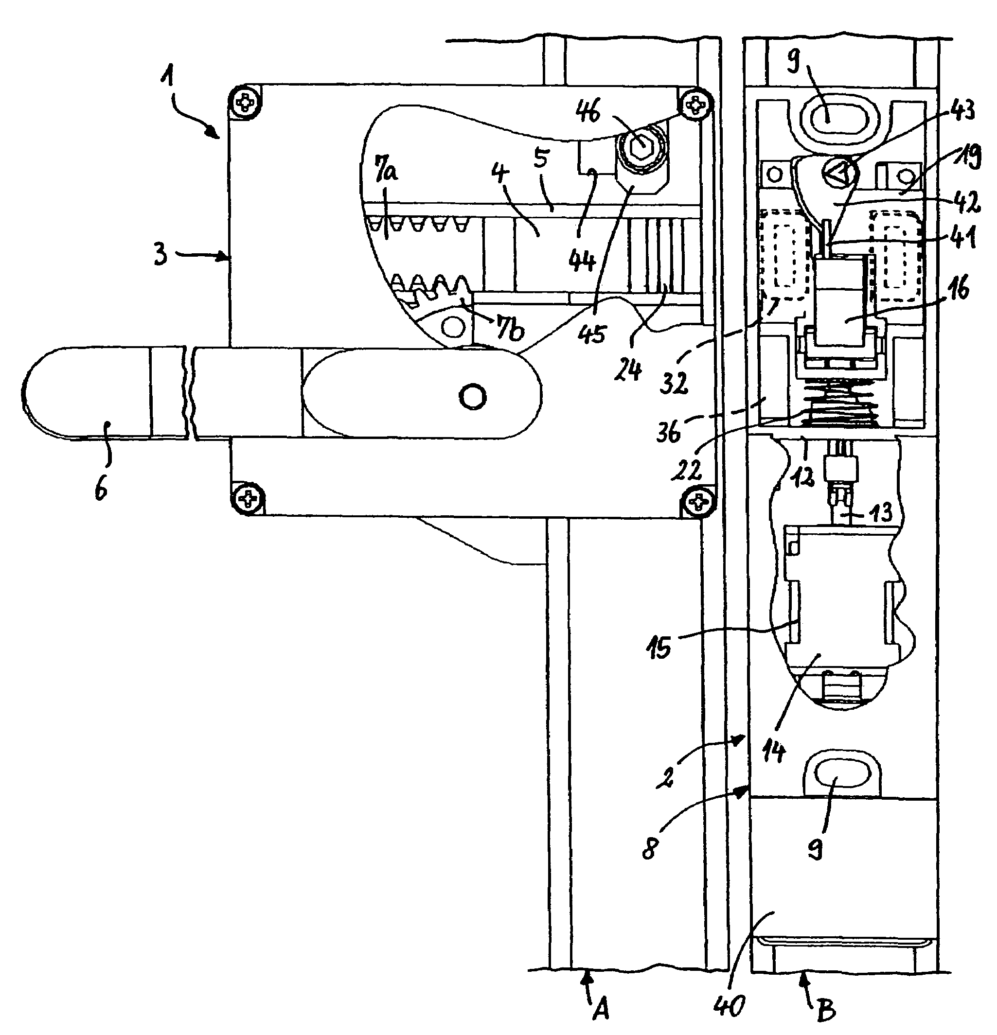
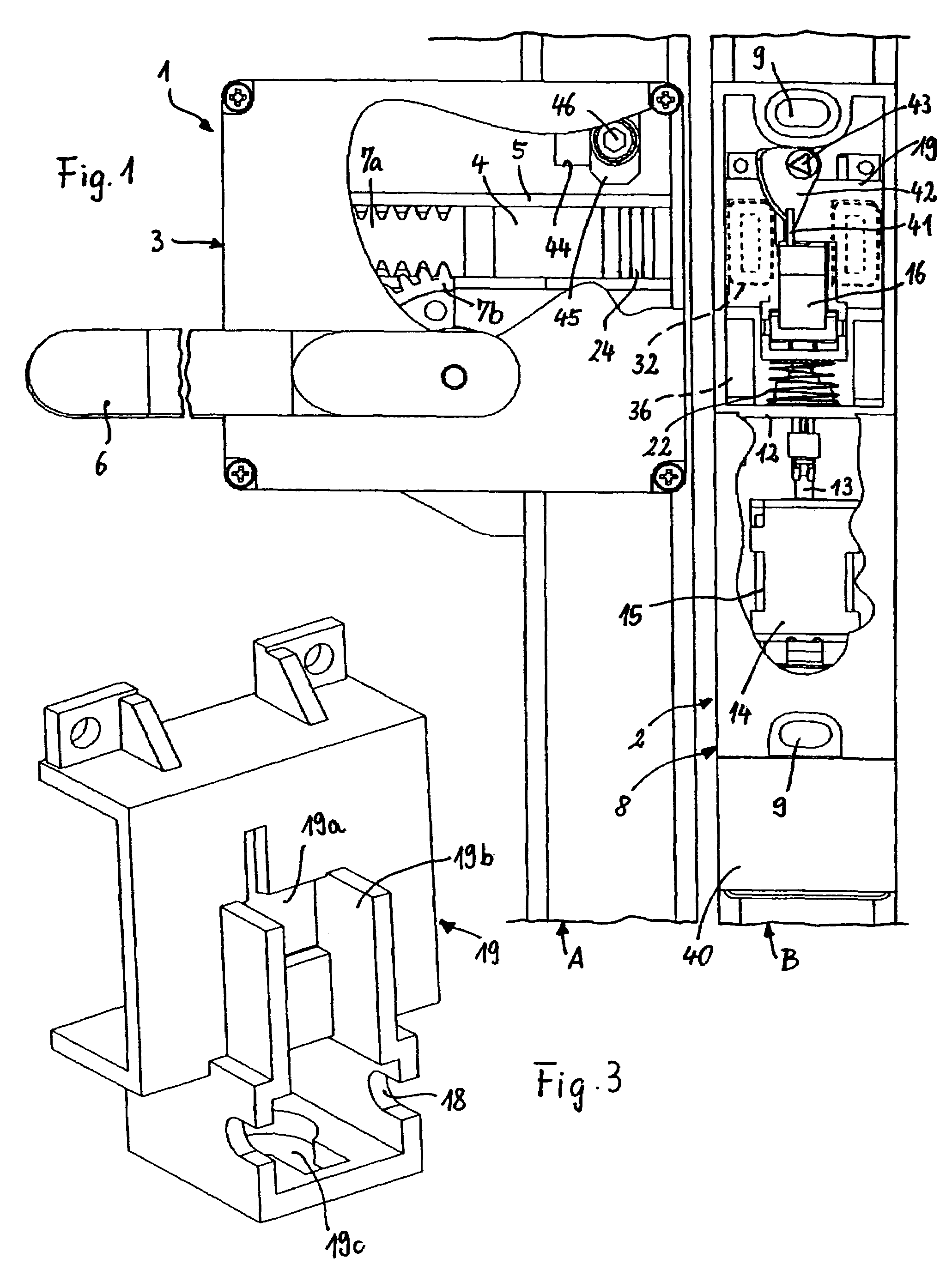
[0023]The safety lock which is illustrated in FIG. 1 comprises an actuator unit 1 and a locking unit 2.

[0024]The actuator unit 1 comprises a housing 3 which can be closed by means of a cover (illustrated in cut-away form) and is fastened on the openable closing-off device A, for example a door, for instance a sliding or pivoting door, or a flap or shutter or the like. In the housing 3, an actuator 4, which is spring-biased into its starting position, is guided in a displaceable manner in a guide 5. The actuator 4 is displaced, for example, by virtue of a handle 6, which is mounted in the housing 3, being pivoted approximately through 90°, this pivoting movement being converted, via a lever drive or a rack-and-pinion drive 7a, 7b, into a linear movement of the actuator 4, with the result that the actuator 4 passes out through a slot provided in the housing 3 (this slot not being visible in the illustration of FIG. 1).

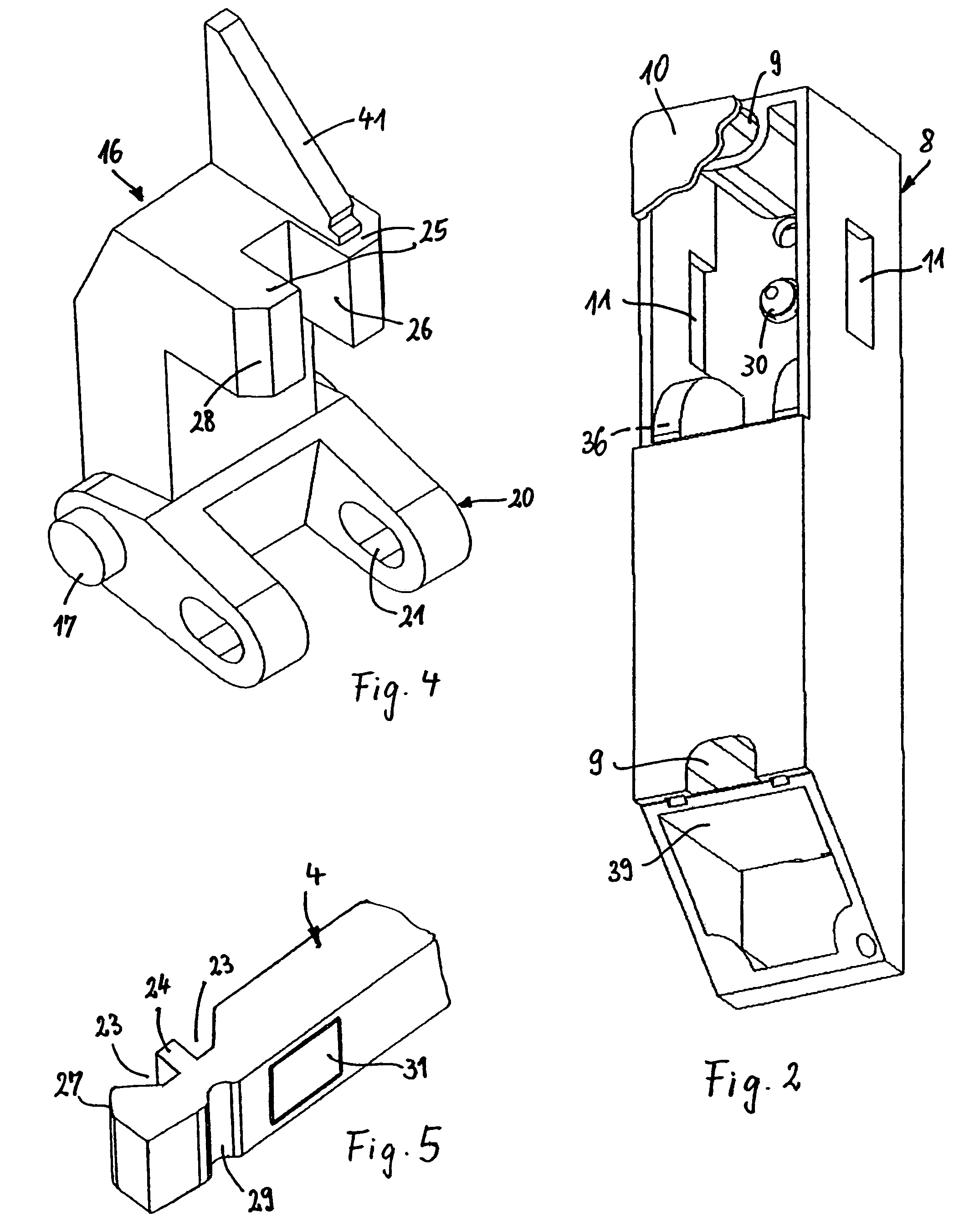
[0025]The locking unit 2 likewise comprises a housing 8, which can ...


PUM


Abstract

A safety lock for a closing-off device which can be opened, has an actuating unit with an actuator which is guided in a displaceable manner, and has a locking unit into which the actuator, with the closing-off device closed, can be pushed and can be locked via an electromagnetically actuable, pivotable catch, by way of interengaging engagement surfaces, the actuator has a trigger element and the locking unit has a response element which, with the actuator pushed in, reacts to the trigger element by emitting an electric signal which triggers the locking action, in the case of which the catch can be pivoted about an axis extending parallel to the movement direction of the actuator, and the engagement surfaces of the catch and of the actuator run perpendicularly to the movement direction.

Description

RELATED APPLICATIONS[0001]This application is a continuation of application Ser. No. 10 / 776,784 filed Feb. 11, 2004, now abandoned which claims priority to German Application No. 103 05 704.8 filed Feb. 12, 2003.FILED OF THE INVENTION[0002]The invention relates to a safety lock for a closing-off device like a door, a flap or shutter as used for limiting the access to restricted areas as housings of machines or enclosures of machinery like robots or the like.DESCRIPTION OF THE RELATED ART[0003]A safety lock for a closing-off device in the form of a door, a flap or shutter or the like is known from published German Patent Application DE 199 34 370 A 1. It comprises an actuator which can be displaced in its longitudinal direction and has a trigger element and a nose. Provided in the housing of a locking unit are a catch, which can be pivoted about an axis transversely to the movement direction of the actuator, and a response element, which responds to the trigger element of the actuato...

Claims


Application Information

Patent Timeline
Patent Type & Authority Patents(United States)
IPC IPC(8): E05C1/06E05B15/02E05B47/00E05B63/04
CPCE05B47/0046E05B63/04E05B2047/0069Y10T70/7068Y10T292/68Y10T292/702Y10T292/699Y10T70/7057Y10T292/1021Y10T292/11
Inventor EICHENAUER, MANFRED
Owner K A SCHMERSAL
Why Eureka
Try Eureka