Light guide plate

a light guide and guide plate technology, applied in the direction of planar/plate-like light guides, lighting and heating apparatus, instruments, etc., can solve the problems of un uniform guide plate b>1/b>, and non-uniform light intensity distribution, so as to prevent bright lines, eliminate brightness variations, and be well-balanced

Active Publication Date: 2008-04-15
CITIZEN ELECTRONICS CO LTD
View PDF9 Cites 40 Cited by
  • Summary
  • Abstract
  • Description
  • Claims
  • Application Information

AI Technical Summary

Benefits of technology

[0017]An object of this invention is to provide a light guide plate for a planar light source that can solve the problems associated with the conventional light guide plates described above, prevent bright lines near the light source or brightness variations and make uniform an intensity distribution of light that has entered into the light guide plate, thereby improving a quality of display image.
[0021]As described above, since one of its side surfaces is made the light incidence face which then forms into the undulated surface portion, the directivity of light that has entered the light guide plate can be corrected, providing a well-balanced characteristic without deviations. As a result, the intensity of light inside the light guide plate can be made uniform, preventing bright lines from being produced near the light source or eliminating brightness variations. This in turn allows a high quality side light type planar light source to be realized by the light guide plate of this invention and LEDs. Further, where the light guide plate of this invention is used as a side light type planar light source for a liquid crystal display, the liquid crystal display can produce a high quality image with reduced brightness variations.

Problems solved by technology

Thus, in the conventional light guide plate 1 which has the light incidence face 1a formed as a flat surface, there is a problem that a distribution of intensity of the light 5 after it enters the light guide plate 1 is ununiform.
In the conventional light guide plate 11 as described above, the light beams 15, 16, 17 that enters the light guide plate 11 from the light incidence face 11a have distorted directivities, giving rise to a problem that the light intensity distribution becomes non-uniform because of the distorted characteristics of the directivities If the light guide plate 11 with an ununiform light intensity distribution is used in a side light type planar light source for a liquid crystal display, there is a problem that bright lines are produced from the light source or the brightness on the display screen varies, significantly degrading an image quality.

Method used


Image

  • Light guide plate
  • Light guide plate
  • Light guide plate

Examples


first embodiment

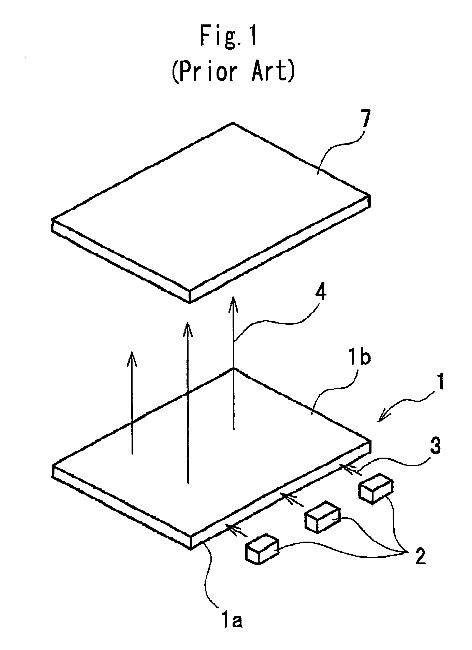
[0045]Now, preferred embodiments of the light guide plate according to this invention will be described in detail by referring to the accompanying drawings. FIG. 8A and FIG. 8B show a side light type planar light source using the light guide plate according to this invention. In this embodiment, constitutional elements identical with the corresponding elements in the conventional light guide plate are given like reference numbers and their detailed descriptions omitted.

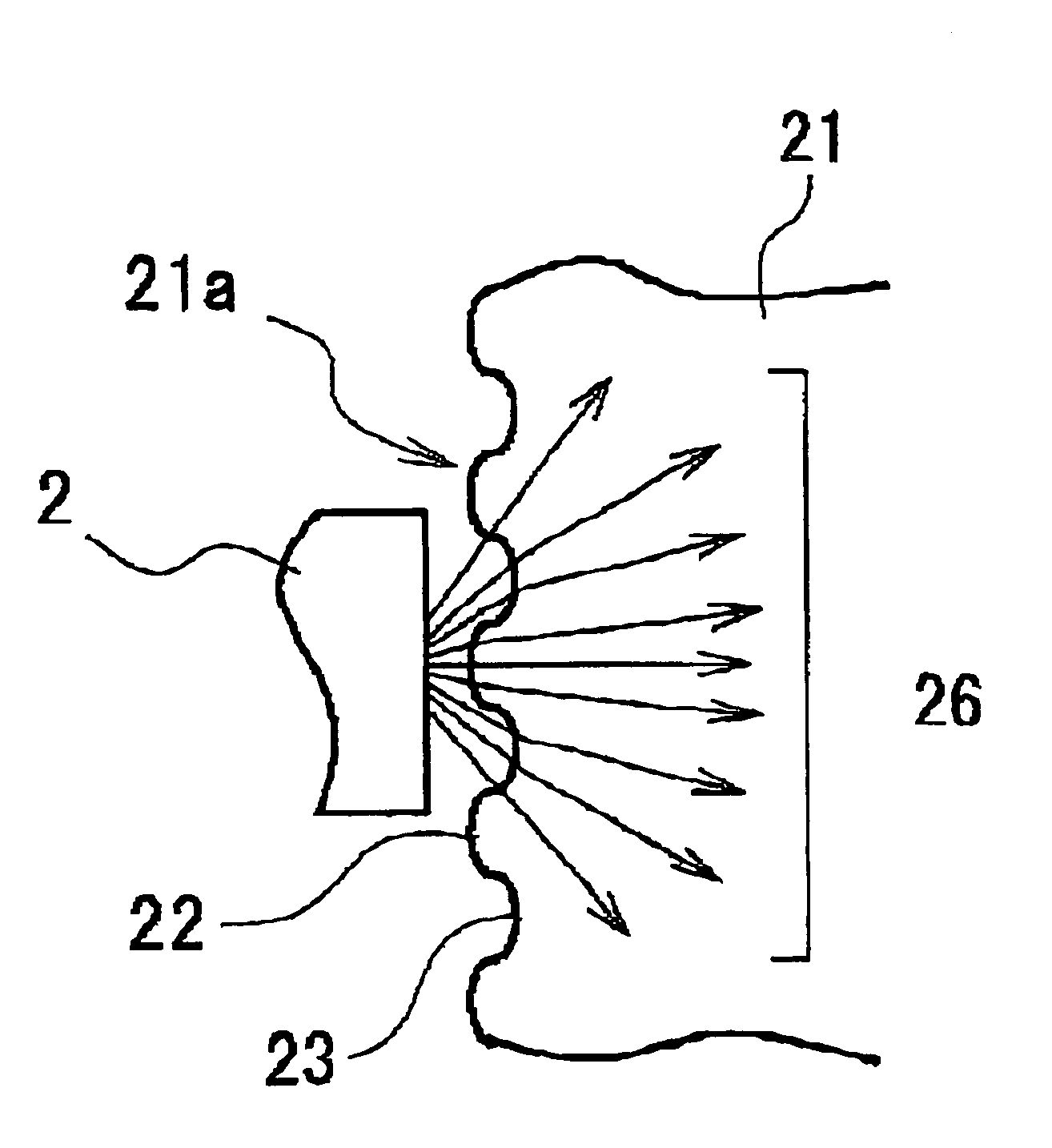
[0046]As shown in FIG. 8A and FIG. 8B, the planar light source in this embodiment has a light guide plate 21 and a light source 2 made up of three light emitting diodes (LEDs). The light guide plate 21 is formed as an almost rectangular prism-shaped plate member that is made by injection-molding a light-transmitting plastic material, such as acrylic resin. The light guide plate 21 has its upper surface formed as a light emitting face 21b. A bottom surface 21c of the light guide plate 21 opposite the light emitting fac...

second embodiment

[0056]While in the first and second embodiment, our descriptions concern the almost rectangular prism-shaped light guide plate 1, the present invention is not limited to this construction. The invention can also be applied to other than the rectangular prism-shaped light guide plate, such as polygonal light guide plates.

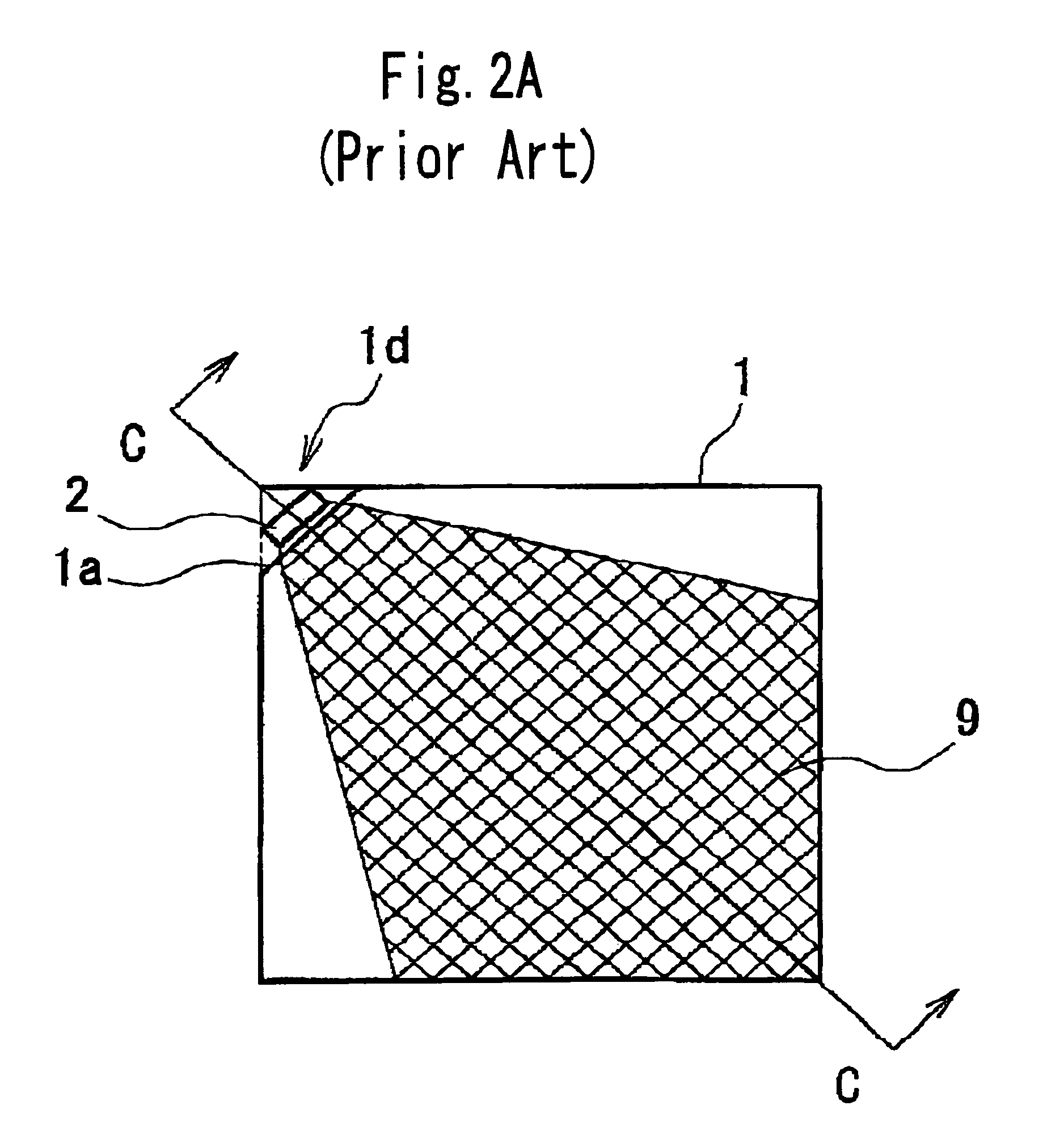
[0057]Further, in the second embodiment the construction has been described in which one corner of the light guide plate is cut off to form a light incidence face and in which a light source made up of one LED is installed to face the light incidence face. This invention can also be applied to side light type planar light sources in which a plurality of light incidence faces are formed on two or more cut-off corner portions or in which a plurality of LEDs are arranged on the light incidence faces.

[0058]In the first and second embodiment, the construction has been described in which the light incidence face, whose cross section is defined by a quadratic curve, forms i...


PUM


Abstract

A light guide plate comprises: a plate ember having a light transmitting capability; and a light incidence face provided on a side surface of the plate member; wherein the plate member changes a path of light emitted from a light source arranged to face the light incidence face and emits planar illumination light from an upper surface of the plate member onto an object to be illuminated; wherein an undulated surface portion is formed on the light incidence face. Further, the undulated surface portion is formed by smoothly connecting curved recessed portions and curved raised portions. This arrangement prevents bright lines from being produced near the light source and also prevents brightness variations, thus making uniform an intensity distribution of light that has entered the light guide plate.

Description

CROSS REFERENCE TO RELATED APPLICATION[0001]The application claims the priority benefit of Japanese Patent Application No. 2004-39086, filed on Feb. 16, 2004, and No. 2004-39087, filed on Feb. 16, 2004, the entire descriptions of which are incorporated herein by reference.BACKGROUND OF THE INVENTION[0002]1. Field of the Invention[0003]The present invention relates to a light guide plate used for a planar light source that illuminates a liquid crystal panel from its back and more particularly to a light guide plate for a planar light source suitably applied to small liquid crystal panels used on cell phones.[0004]2. Description of Related Art[0005]A growing number of thin, easy-to-see liquid crystal displays having a backlight mechanism are being used as displays on small, thin information devices, such as notebook word processors or computers, cell phones and portable TV sets. Such a backlight mechanism uses a planar light source to illuminate an entire surface or a liquid crystal p...

Claims


Application Information

Patent Timeline
Patent Type & Authority Patents(United States)
IPC IPC(8): F21V7/04F21V8/00G02B6/00
CPCG02B6/0016G02B6/0018G02B6/0036G02F1/1335
Inventor MIYASHITA, JUNJI
Owner CITIZEN ELECTRONICS CO LTD
Why Eureka
Try Eureka