Self-regulating endless climbing wall

a technology of self-regulation and climbing wall, which is applied in the field of exercise equipment, can solve the problems of heavy and expensive equipment to purchase and operate, remain heavy and/or complex, and achieve the effects of reducing tension, increasing rotational slippage of belts, and reducing the number of steps

Inactive Publication Date: 2008-04-15
BROWN GEORGE T
View PDF6 Cites 17 Cited by
  • Summary
  • Abstract
  • Description
  • Claims
  • Application Information

AI Technical Summary

Benefits of technology

[0009]A tensioning shoe engages with the inner surface of the belt through the open back surface of the form, and a mechanism, coupled to the tensioning shoe, is operative to a) relieve tension on the belt as a user climbs upwardly, thereby increasing rotational slippage of the belt around the form, and b) increase tension on the belt as a user moves downwardly, thereby reducing or terminating rotational slippage of the belt around the form.
[0010]In the preferred embodiment, the tensioning shoe is a generally horizontal bar having a lengthwise convex surface urged against the inner surface of the belt. A pair of pivoting levers are provided, each having one end coupled to a climber and a second end coupled to the tensioning shoe such that, as a climber ascends the belt, the levers are raised, reducing the frictional engagement of the inner surface of the belt against the form, and as a climber moves downwardly on the belt, the levers are lowered, increasing the frictional engagement of the inner surface of the belt against the form.

Problems solved by technology

A drawback of typical linked-panel type climbers is that the rollers are motor-driven, resulting in a piece of equipment which is heavy and expensive to purchase and operate.
Although these and other prior-art systems attempt to regulate climbing motion without the use of electricity, there nevertheless remain heavy and / or complex.

Method used


Image

  • Self-regulating endless climbing wall
  • Self-regulating endless climbing wall
  • Self-regulating endless climbing wall

Examples


Embodiment Construction

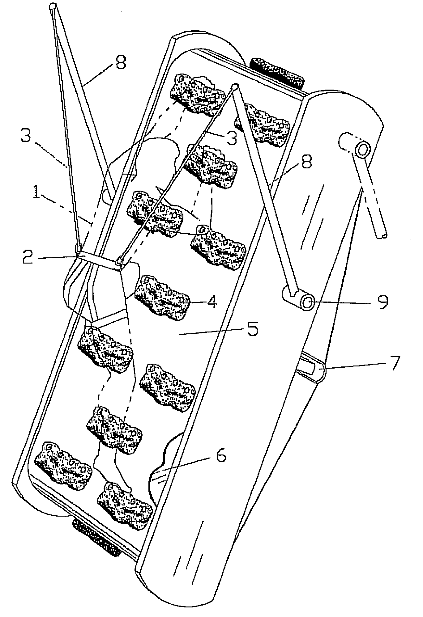
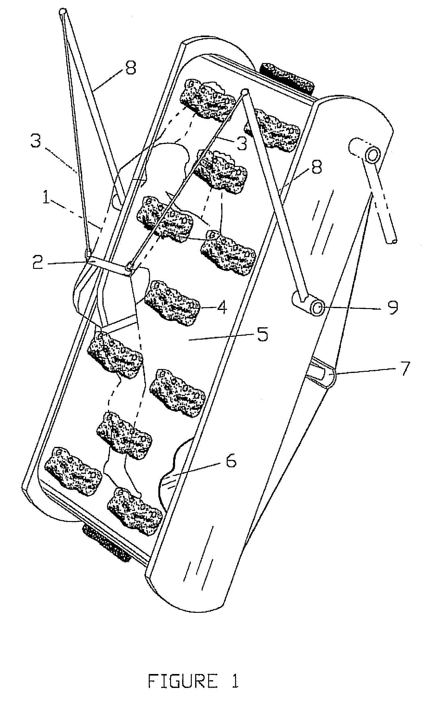
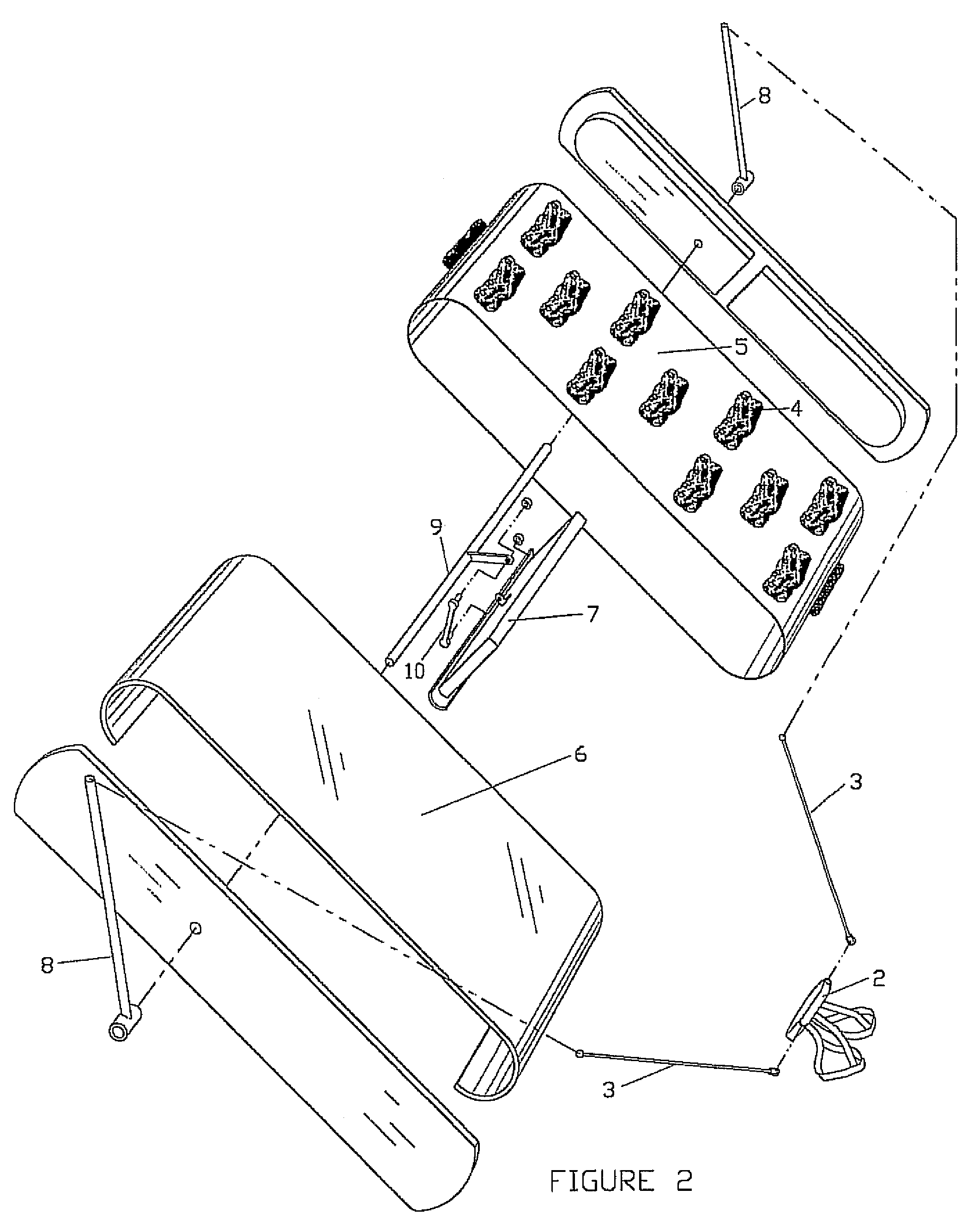
[0017]Referring now to the drawings, FIGS. 1, 2 and 3 illustrate the preferred embodiment of the invention. FIG. 1 shows the invention assembled with the climber in position on a climbing surface, and with support frame portions removed for enhanced clarity. FIG. 2 is an exploded view of the preferred embodiment; and FIG. 3 shows geometrical and mathematical relationships associated with the belt-tensioning system.

[0018]The unit comprises a continuous belt 5 having an outer surface with the exposed hand and foot holds 4, and an inner surface against which a tensioning shoe 7 is used to adjust the tension of the belt and, hence, frictional contact between the belt and the form. The invention is not limited in terms of the type, style or number of hand / foot holds 4, and may use any protruding features as desired or required. Indeed, the belt may be provided with mounting holes or grommets so that different holds can be fastened in a variety of arrangements. The belt could also have a ...


PUM


Abstract

An improved simulated climbing wall provides a self-regulating endless climbing surface. The structure includes a form including upper and lower at least partially cylindrical outer surfaces, a planar forward surface, and an open back surface. A continuous belt includes an inner surface and an outer surface. The inner surface is disposed in sliding engagement with the cylindrical surfaces and planar forward surface of the form, and the outer surface of the belt includes a plurality of raised features configured for climbing by a user. A tensioning shoe engages with the inner surface of the belt through the open back surface of the form, and a mechanism, coupled to the tensioning shoe, is operative to a) relieve tension on the belt as a user climbs upwardly, thereby increasing rotational slippage of the belt around the form, and b) increase tension on the belt as a user moves downwardly, thereby reducing or terminating rotational slippage of the belt around the form. In the preferred embodiment, a pair of pivoting levers are provided, each having one end coupled to a climber and a second end coupled to the tensioning shoe such that, as a climber ascends the belt, the levers are raised, reducing the frictional engagement of the inner surface of the belt against the form, and as a climber moves downwardly on the belt, the levers are lowered, increasing the frictional engagement of the inner surface of the belt against the form.

Description

REFERENCE TO RELATED APPLICATION[0001]This application claims priority from U.S. Provisional Patent Application Ser. No. 60 / 597,676, filed Dec. 16, 2005, the entire content of which is incorporated herein by reference.FIELD OF THE INVENTION[0002]This invention relates generally to exercise equipment and, in particular, to a simulated climbing wall having a self-adjustment mechanism.BACKGROUND OF THE INVENTION[0003]Many exercise and recreational centers are now equipped with simulated climbing walls. Devices of this type include both larger, stationary structures as well as more compact “endless walls.” Conventional endless wall climbers consist of large linked panels dressed over upper and lower rollers. The panels have an outer surface with hand-holds or other features that a user ‘climbs’ as the panels rotate.[0004]A drawback of typical linked-panel type climbers is that the rollers are motor-driven, resulting in a piece of equipment which is heavy and expensive to purchase and op...

Claims


Application Information

Patent Timeline
Patent Type & Authority Patents(United States)
IPC IPC(8): A63B7/04A63B9/00
CPCA63B22/001A63B22/04A63B69/0048A63B22/0242A63B2024/0093A63B2220/13
Inventor BROWN, GEORGE T.
Owner BROWN GEORGE T
Why Eureka
Try Eureka