Proximity sensor interface

a sensor interface and proximity technology, applied in the field of inductive sensing, can solve problems such as failure of inductive sensors

Active Publication Date: 2008-04-15
SIMMONDS PRECISION PRODS
View PDF6 Cites 21 Cited by
  • Summary
  • Abstract
  • Description
  • Claims
  • Application Information

AI Technical Summary

Problems solved by technology

If a wire fault occurs in any signal line transmitting said driving signal or said return signal and causes said any signal line to fail to ground, there may be failure of said inductive sensor, said failure of said inductive sensor being a trigger event for detecting a failed signal line.

Method used


Image

  • Proximity sensor interface
  • Proximity sensor interface
  • Proximity sensor interface

Examples


Embodiment Construction

)

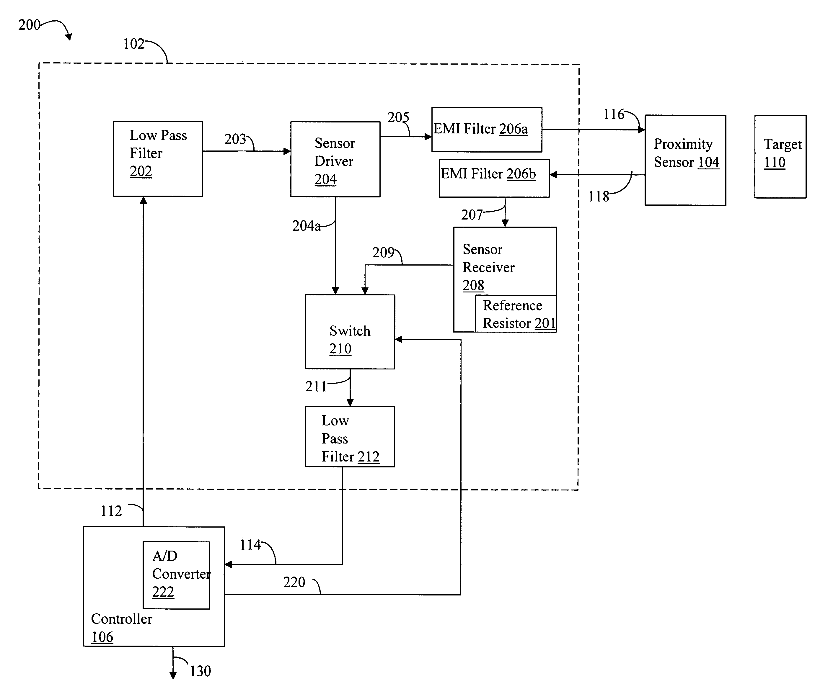
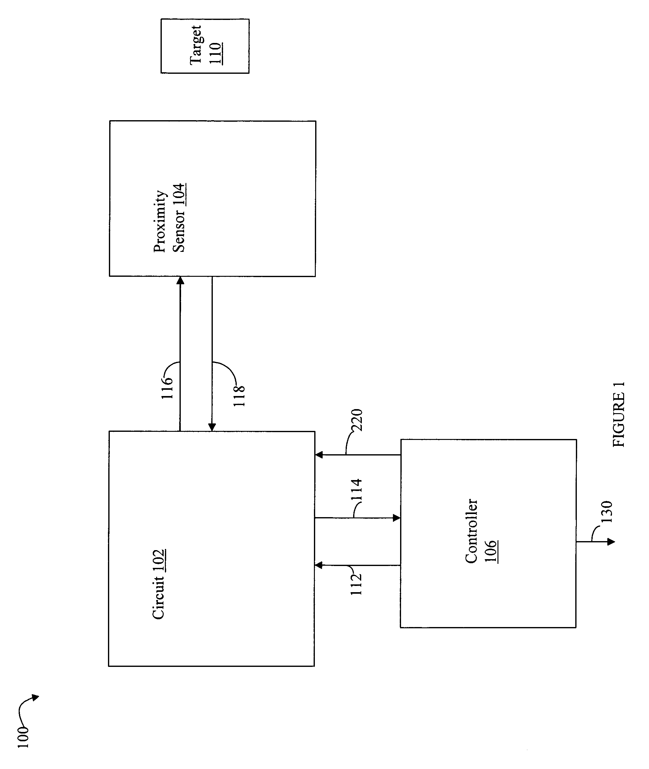
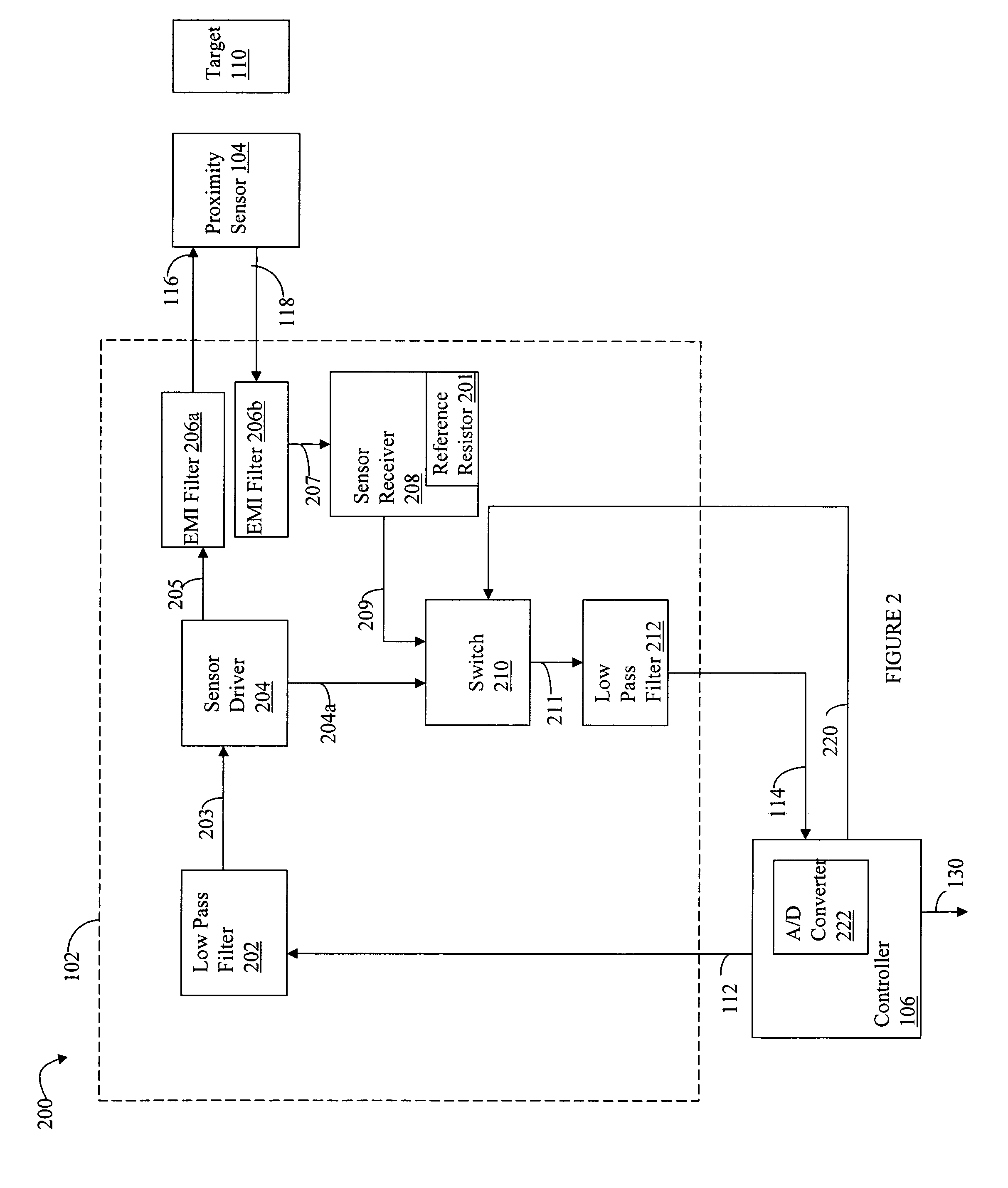
[0015]Referring now to FIG. 1, shown is an example of an embodiment of a functional block diagram of components used in connection with the techniques described herein for proximity sensing. The example 100 includes a circuit 102, a controller 106, a proximity sensor 104 and a target 110. The controller 106 produces an analog electrical signal on line 112 which is an input to the circuit 102. The circuit 102 generates a driving signal on line 116 which is input to the proximity sensor 104. The proximity sensor generates a return signal on line 118 to the circuit 102. The circuit 102 produces an output analog signal on line 114 to the controller 106. The circuit 102 converts a sensor current signal received on line 118 from the sensor 104 to an equivalent voltage signal which is returned to the controller on line 114. Based on the signal returned on line 114, processing may be performed by the controller in connection with making a determination regarding proximity of the target 110...


PUM


Abstract

A first measured value is determined which is associated with the proximity of a target to an inductive sensor. A first voltage signal having a first amplitude is generated. The first voltage signal is provided as a driving signal to the inductive sensor. A sensor current signal is received as a return signal output from the inductive sensor. The sensor current signal has an amplitude proportional to a proximity of the target to the inductive sensor. The sensor current signal is converted to a corresponding second voltage signal having a second amplitude. A differential measuring technique is used to determine the first measured value in accordance with relative amplitudes of said first voltage signal and said second voltage signal.

Description

BACKGROUND[0001]1. Technical Field[0002]This application generally relates to inductive sensing, and more particularly to inductive sensing to measure the proximity of a target object.[0003]2. Description of Related Art[0004]Different sensing techniques may be used in connection with proximity sensors to determine the proximity of a target. Inductive sensing techniques may be used with a proximity sensor that detects the proximity of a metal target. Depending on the closeness of the metal target, the magnetic characteristics of the sensor change. Proximity sensors may be used in a variety of different applications and environments. One example application and use of a proximity sensor is in the aviation industry. Proximity sensors may be used in ascertaining a particular position of airplane components. For example, a metal target may be located on a component. The proximity sensor may be used to determine magnetic characteristics based on the proximity of the sensor to the metal ta...

Claims


Application Information

Patent Timeline
Patent Type & Authority Patents(United States)
IPC IPC(8): G01B7/14
CPCG01D5/2013G01D5/202
Inventor MAIER, LAWRENCE CARL
Owner SIMMONDS PRECISION PRODS
Why Eureka
Try Eureka