Process for plotting the shape of a contour of a previously machined ophthalmic lens

Inactive Publication Date: 2008-04-15
ESSILOR INT CIE GEN DOPTIQUE
View PDF5 Cites 2 Cited by
  • Summary
  • Abstract
  • Description
  • Claims
  • Application Information

AI Technical Summary

Benefits of technology

[0017]The invention aims to resolve in particular the abovementioned drawbacks and to allow a machining of the lens or a reworking of the latter which is both simpler, more reliable and more precise, whilst allowing substantial gains in productivity.

Problems solved by technology

However, it may then be noticed that the lens is not perfectly matched to said ring, which means that an additional reworking operation is required, which consists of removing again a certain quantity of material from the lens along its rim in order to match the ring of the frame.
However, such a manual reworking operation involves, for the optician, constant trips between the grinding machine and the frame to check if the lens corresponds to the ring of the frame, which is tedious.
Moreover, such a manual reworking is, by nature, imprecise, and it happens that defects not visible to the naked eye are detrimental to the firm grip of the lens in the ring of the frame.
The imprecision of this manual reworking can also lead to the lens being discarded if it has incorrectable defects.
Generally, the fitting of the “gland or holding means” is carried out elsewhere by means of a costly special machine.

Method used


Image

  • Process for plotting the shape of a contour of a previously machined ophthalmic lens
  • Process for plotting the shape of a contour of a previously machined ophthalmic lens
  • Process for plotting the shape of a contour of a previously machined ophthalmic lens

Examples


Embodiment Construction

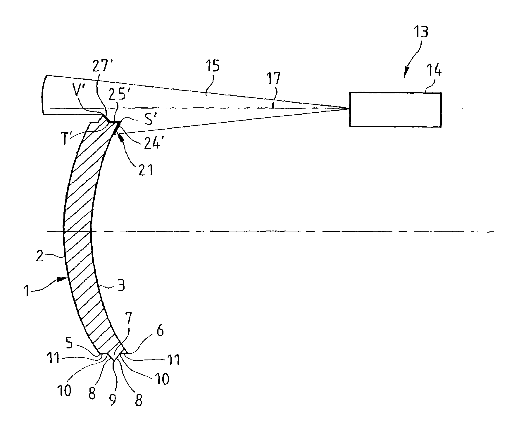
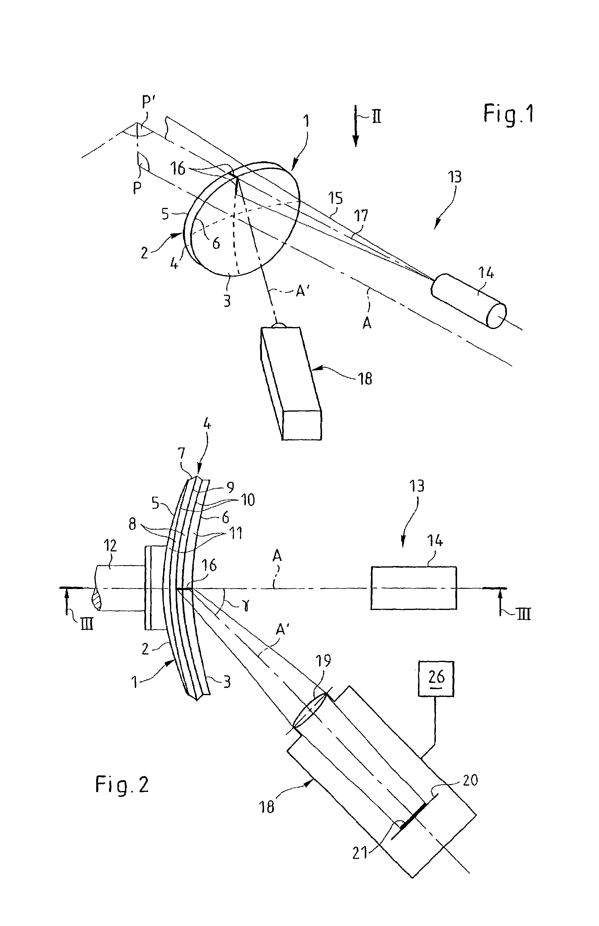
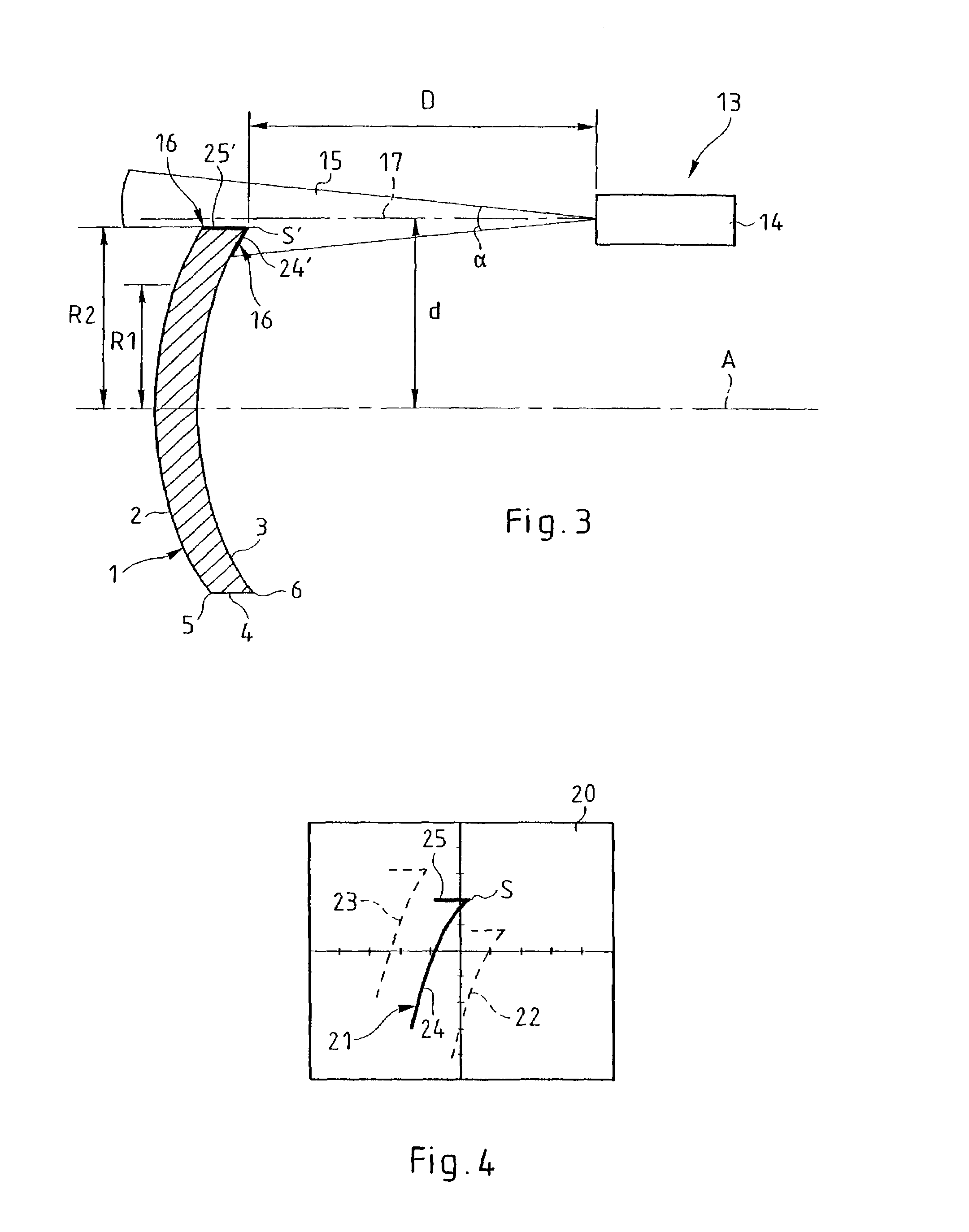
[0051]In FIG. 1 an ophthalmic lens 1 is shown which has two optical surfaces constituted respectively by a so-called front face 2 and a so-called rear face 3 which are opposed, linked by a rim 4 which was initially cylindrical with a circular profile but which, after a machining operation, has a contour approximately corresponding to that of a ring of the spectacle frame in which this lens 1 is intended to be mounted.

[0052]The lens 1 has at the junction of its rim 4 and its front face 2 a peripheral front edge 5 which radially delimits the front face 2 and, at the junction of its rim 4 and its rear face 3, a peripheral rear edge 6 which radially delimits the rear face 3.

[0053]In a first case, the rim 4 of the lens 1 is cylindrical because it has been subjected to only one trueing operation and must also be subjected to one or more complementary finishing operations.

[0054]In a second case, the rim 4 of the lens 1 is also cylindrical, but for a different reason: it has been subjected ...


PUM


Abstract

Process for plotting the shape of a contour (5, 6) of a previously machined ophthalmic lens (1), which comprises the steps of:illuminating an optical face (2, 3) of the lens (1) with a flat light beam (15) to form a linear light spot (16) on this face (2, 3), such that the beam (15) extends beyond said face (2, 3) and illuminates the contour (5, 6);forming on the optical reception element (18) an image of the light spot (16);rotating the lens (1) about an axis (A);scanning the contour (5, 6) with the light beam (15);plotting concomitantly on the optical reception element (18) the successive positions of at least one single point of this image corresponding to the illuminated point of the contour (5, 6);deducing the shape of the contour (5, 6).

Description

BACKGROUND OF THE INVENTION[0001]1. Field of the Invention[0002]The invention relates to the machining of ophthalmic lenses, i.e. to the set of operations aimed at giving the rim of the lens a predetermined shape corresponding as precisely as possible to that of the ring of a spectacle frame in which the lens is intended to be mounted.[0003]2. Description of the Related Art[0004]It will be recollected that a lens, mounted on a support shaft, subjected firstly to a trueing operation in which it is ground along its rim until the latter has roughly—i.e., generally, with allowance—the predetermined shape, then one or more finishing operations consisting of refining the shape of the rim, and, optionally, giving it a particular structural configuration, for example by machining a bevel or, on the other hand, a groove on the rim.[0005]As soon as these operations have been carried out, the lens is removed from its support shaft to be mounted in the ring of the frame. However, it may then be...

Claims


Application Information

Patent Timeline
IPC IPC(8): G06F19/00G02C13/00B24B9/14G01B11/25
CPCB24B9/14G01B11/2522
Inventor GUILLERMIN, LAURENTMILLET, SYLVAINE
Owner ESSILOR INT CIE GEN DOPTIQUE
Why Eureka
Try Eureka