Cutting guide and method of using the same

a technology of cutting guide and guide, which is applied in the direction of metal-working holders, positioning apparatuses, supports, etc., can solve the problems of difficulty in cutting crown mouldings, complex cuts, and difficulty in various types of cutting planks, and achieves the effect of easy and simple operation

Active Publication Date: 2008-04-22
BERTHIAUME RAYMOND
View PDF28 Cites 11 Cited by
  • Summary
  • Abstract
  • Description
  • Claims
  • Application Information

AI Technical Summary

Benefits of technology

[0010]Particularly, the present invention relates to a cutting guide allowing for positioning of a piece of material such as a crown moulding according to its final installation orientation relative to the blade of a mitre cutting tool.
[0011]Advantageously, the present invention relates to a cutting guide that is easy and simple to operate, that does not require mechanical attachment of the piece being cut and does not require recourse to complicated calculations or other complex procedures.
[0039]Advantageously, the invention relates to a cutting guide as hereinabove defined, characterised in that a portion of the first and second component ends are bevelled (for example at 45 degrees). This characteristic allows positioning of the cutting guide more closely to the blade of the cutting tool hence increasing the stability of the cutting guide and of the piece to be cut.

Problems solved by technology

The cutting of various types of planks, such as “OGEE”—type crown mouldings may prove to be particularly tedious.
Indeed, since crown mouldings are designed so as to be mounted at the intersection of a wall and a ceiling, they typically require complex cuts in order to produce the desired assembly angle.
The difficulty in cutting crown mouldings is due, at least in part, to the fact that the mouldings are typically mounted at a predetermined angle (i.e. 38°, 45° or 52°) between the wall and the ceiling and must also be cut at an angle in order to follow the angle of the wall corners.
However, this mitre box suffers from numerous drawbacks.
This may, in turn, lead to blockage of the saw blade and / or the moulding.
It may also potentially lead to injuries.
Furthermore, since clamps are required to secure the moulding in place, it becomes impossible to cut a portion of moulding inferior in length to the spacing between the abutment points.
The supporting structure, however, does not allow for orientation of the moulding according to its final installation position.
Furthermore, since the moulding is angularly displaced relative to the blade, the portion of the moulding being cut will either interfere with the support 31, or be cumbersome to use.
This support structure does not however allow for orientation of the moulding according to its final installation position.
Accordingly, none of the prior art documents provides a cutting guide that allows for pieces such as a crown moulding to be cut according to their final installation orientation while reducing the risks of errors in the orientation of the cut that, the cutting guide being easy and simple to use without requiring that the piece being cut be mechanically secured and without requiring recourse to complicated calculations or other complex procedures.
Furthermore, none of the prior documents allows for the realisation of a cutting guide that is usable with existing meter-type cutting tools, that is safe to use and also reduces the risk or damaging the moulding.

Method used


Image

  • Cutting guide and method of using the same
  • Cutting guide and method of using the same
  • Cutting guide and method of using the same

Examples


Embodiment Construction

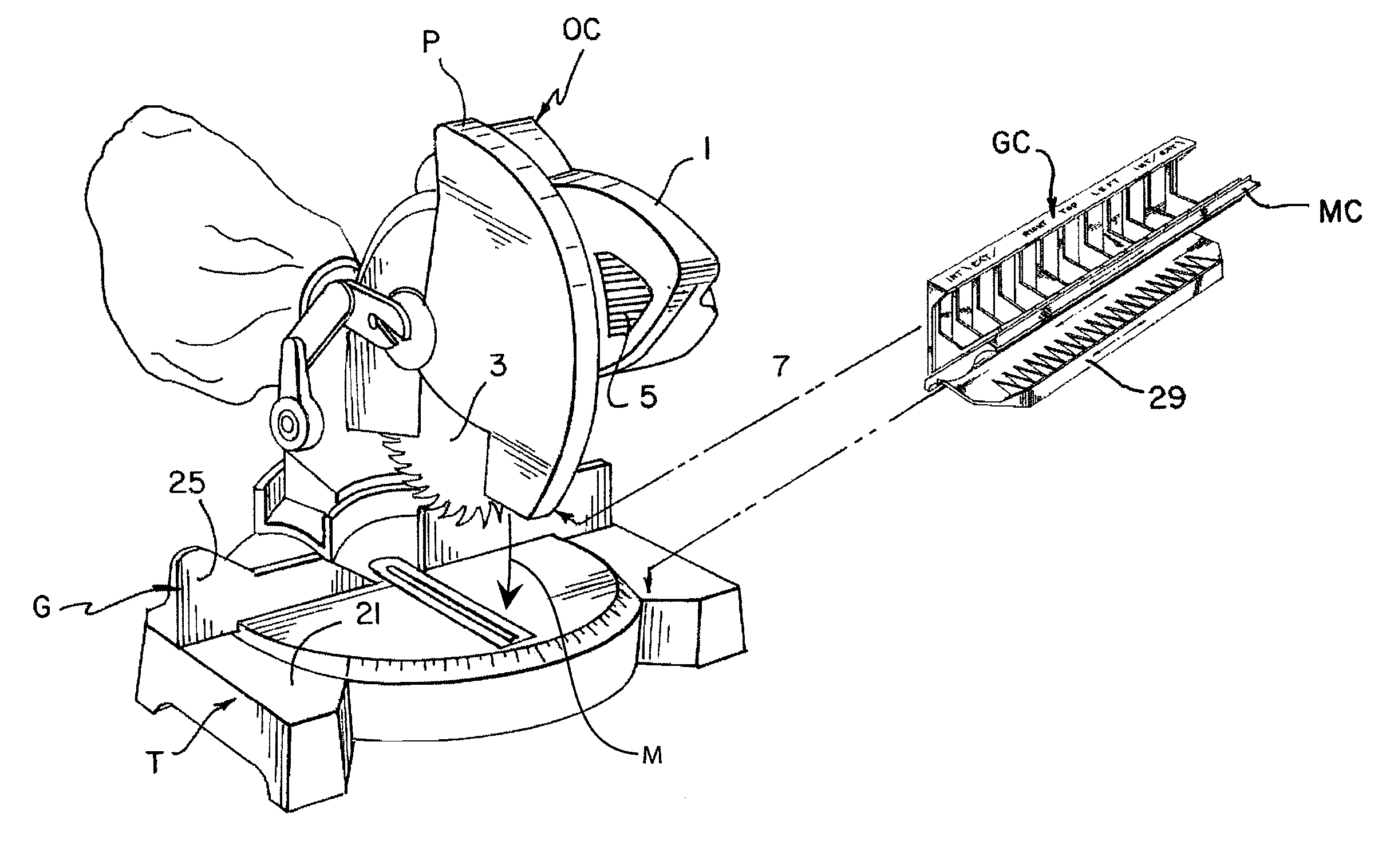
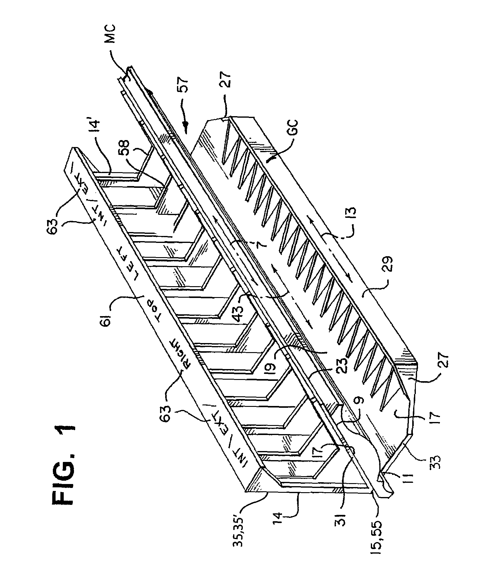
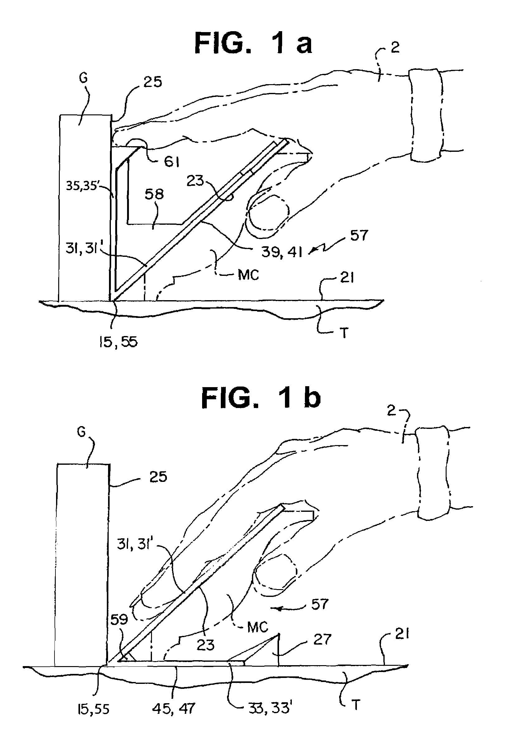
[0065]In accordance with a preferred aspect of the invention, the latter concerns a cutting guide “GC” allowing for precision cutting of pieces (such as planks) of various materials and more particularly of crown mouldings “MC” such as “OGEE”-type mouldings or analogous mouldings (for example, mouldings for cornices, shelves, or the like.

[0066]More particularly, the invention relates to a cutting guide “GC” allowing for the positioning of a crown moulding “MC” (finely carved or not) according to its final installation orientation (see FIG. 8), relative to the blade of a cutting tool “OC” (see FIGS. 2, 2a, 7, 12, and 13). The cutting tool “OC” is provided with a substantially horizontal working table “T”, a substantially vertical guide “G” and means “M” for angularly positioning the blade relative to the guide “G”. The working table “T” and the guide “G” form orthogonal planes 21 and 25 (see FIGS. 2 and 12).

[0067]Preferably, as illustrated in FIGS. 2, 2a, 7, 12, and 13, the cutting t...


PUM

PropertyMeasurementUnit
angleaaaaaaaaaa
angleaaaaaaaaaa
angleaaaaaaaaaa

Abstract

A cutting guide having a component defining a first plane positionable substantially parallel to a working table of a cutting tool and a second plane, the second plane forming a predetermined angle inferior to 90 degrees relative to the first plane so as to receive at least in part a piece to cut and orienting the same according to a predetermined inclined plane. The cutting guide also includes an adapter allowing for modification of the predetermined angle, the adapter being releasably mountable to the component so that one of the faces of the adapter defines a new inclined plane.

Description

FIELD OF THE INVENTION[0001]The present invention relates to cutting guides for cutting various types of materials having various configurations and, in particular, to a cutting guide for cutting crown mouldings and the like. The cutting guide allows for the positioning on conventional mitre-type cutting tools of mouldings such as a crown moulding according to the final installation orientation of the moulding without requiring elaborate calculations.[0002]The present invention also relates to a method of using the cutting guide in accordance with the present invention.BACKGROUND OF THE INVENTION[0003]The cutting of various types of planks, such as “OGEE”—type crown mouldings may prove to be particularly tedious. Indeed, since crown mouldings are designed so as to be mounted at the intersection of a wall and a ceiling, they typically require complex cuts in order to produce the desired assembly angle. The difficulty in cutting crown mouldings is due, at least in part, to the fact th...

Claims


Application Information

Patent Timeline
Patent Type & Authority Patents(United States)
IPC IPC(8): B26D7/01B23Q3/00B23D47/04B27B27/04B27B27/06B27G5/02
CPCB23D47/04B27B27/04B27B27/06B27G5/02B27G5/026Y10T83/7697Y10T83/762Y10T83/7788Y10T83/76Y10T83/7647Y10T83/7593Y10T83/7587Y10T83/748Y10T83/8773Y10T83/7573
Inventor BERTHIAUME, RAYMOND
Owner BERTHIAUME RAYMOND
Why Eureka
Try Eureka