Impact absorption structure of vehicle seat

a technology of impact absorption and vehicle seat, which is applied in the direction of vehicle components, pedestrian/occupant safety arrangements, vehicle arrangements, etc., can solve the problems of causing a corresponding great impact to the whole seat, damage or breakage of the mechanical parts or linkage of such seat height adjustment devices, and difficulty in adjustmen

Inactive Publication Date: 2008-04-22
TACHI S CO LTD
View PDF11 Cites 23 Cited by
  • Summary
  • Abstract
  • Description
  • Claims
  • Application Information

AI Technical Summary

Benefits of technology

[0012]In view of the above-stated drawbacks, it is a purpose of the present invention to provide an improved impact absorption structure of vehicle seat which is simplified in structure and directly applicable to a closed cross-section of side frame member of seat cushion frame

Problems solved by technology

When a rear-end collision or a backward collision defined above occurs to a vehicle, a great load is applied from a seat occupant to a seat in the vehicle in a backward direction, thus creating a corresponding great impact to a whole of the seat.
In that case, it is highly possible that the mechanical parts or linkage of such seat height adjustment device or a connection portion between the seat cushion frame and a floor will be damaged or broken.
However, in this shock absorption structure of seat-back side frame members, it is difficult to adjust and define the deformable area in an optimum size for each different seat back, and further, there is no disclosure for provision of means for limiting backward inclination of the seat back in the case of the deformable area being deformed to allow such backward inclination.
Hence, it is more likely than not that the seat back will be subjected to excessive backward inclination in a collision case.
In this particular sort of seat, each side frame member of the seat cushion frame is naturally reduced in its height-wise thickness and therefore decreases its rigidity.
Such shock absorption structure is defective in that the thus-processed flange portion of the side frame member does not serve its reinforcing and protection functions.
That is, the deformable region given in the upper flange portion of side frame member is found defective in decreasing its reinforcement for the upper side of the side frame member itself and does not protect the adjacent trim cover and padding of seat cushion.

Method used


Image

  • Impact absorption structure of vehicle seat
  • Impact absorption structure of vehicle seat
  • Impact absorption structure of vehicle seat

Examples


Embodiment Construction

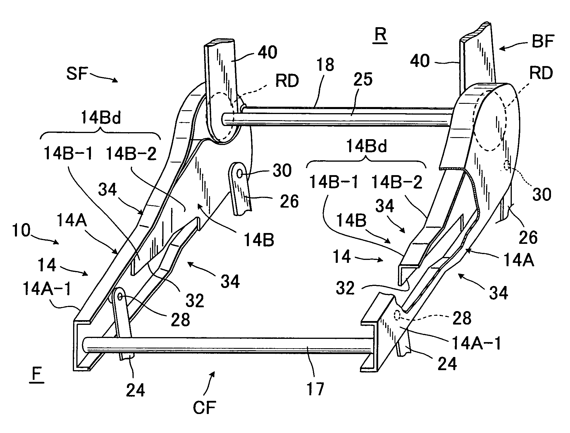
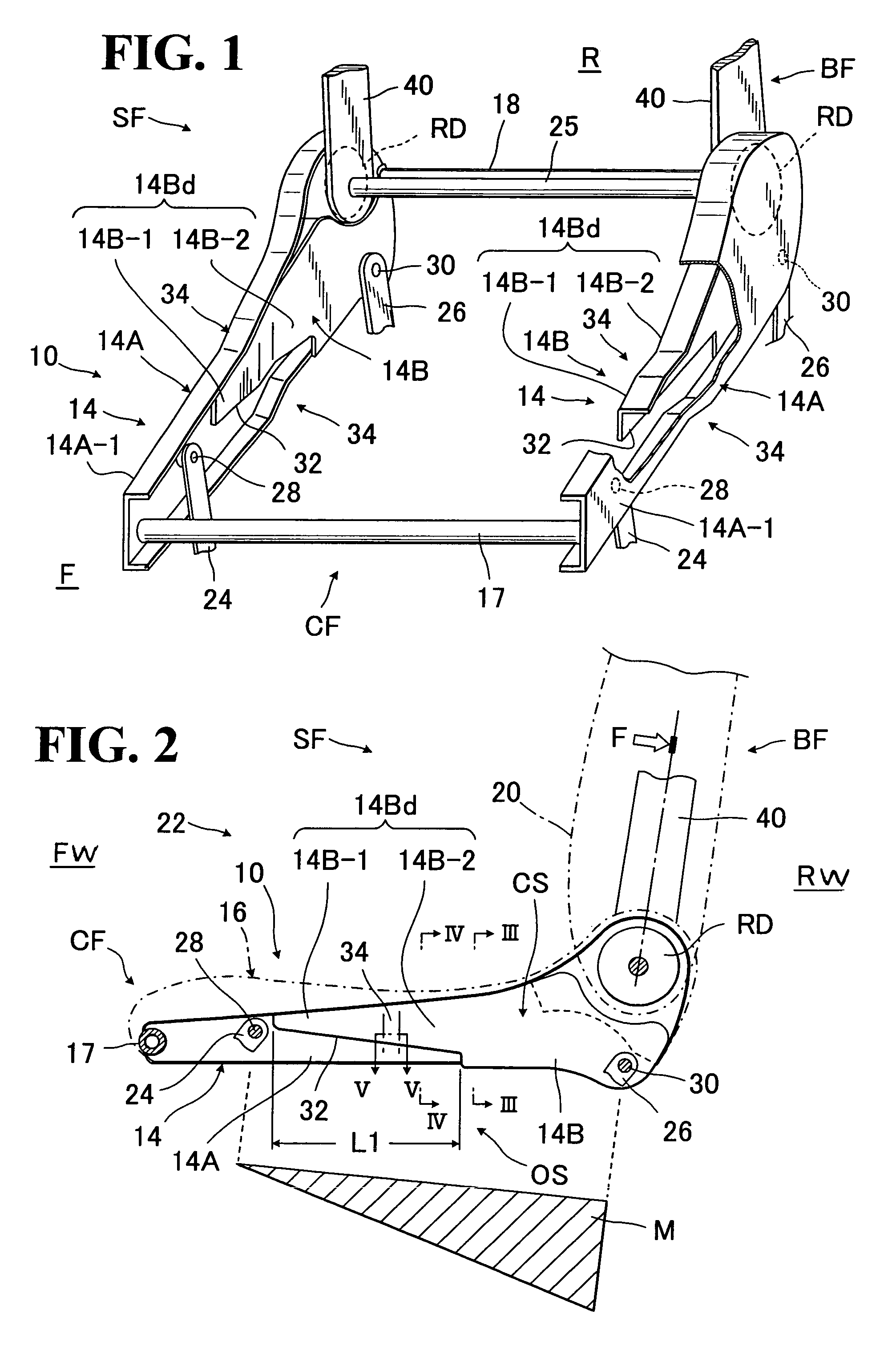
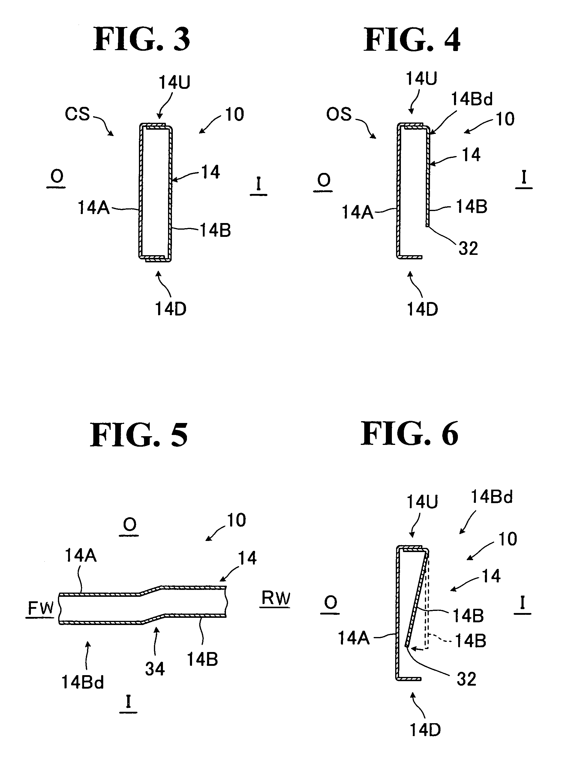
[0028]Referring to FIGS. 1 to 6, there is illustrated a preferred embodiment of impact absorption structure of vehicle seat, as generally designated by (10), in accordance with the present invention.

[0029]FIG. 1 shows, in perspective, a seat framework (SF) used in this particular embodiment, which is intended for better understanding of the present invention, but it has to be upheld to form a vehicle seat (22). Hence, it is to be understood that the seat framework (SF) corresponds to a vehicle seat (22) to which the present invention is applied. The seat framework (SF) typically comprises: a seat back frame (BF) corresponding to a seat back (20) of the vehicle seat; and a seat cushion frame (CF) corresponding to a seat cushion (16) of the vehicle seat, with a pair of known reclining devices (RD) (RD) operatively provided between those two frames (BF) (CF) for allowing for adjustable inclination of the seat back. Designation (25) denotes a connecting rod operatively connected with th...


PUM


Abstract

Impact absorption structure is provided in side frame element of seat cushion frame, wherein the side frame element is basically of a closed cross-section portion therein, including forward and backward support points therein. In the structure, an opened cross-section area is defined in the closed cross-section by forming a cut-away portion in a lower part of a forward local region of such closed cross-section portion between the forward and backward support points, so that the opened cross-section area is deformable at said cut-away portion by a great load transmitted from a seat back frame thereto, thereby absorbing a corresponding impact.

Description

BACKGROUND OF THE INVENTION[0001]1. Field of the Invention[0002]The present invention relates to an impact absorption structure of vehicle seat which is so designed that a local part of seat frame is deformable to absorb an impact caused by a great load applied to the seat in the case of a rear-end collision, or in the case of a backward collision wherein, when a vehicle runs backwardly, a backward side of vehicle collides with something hard or other vehicle.[0003]2. Description of Prior Art[0004]When a rear-end collision or a backward collision defined above occurs to a vehicle, a great load is applied from a seat occupant to a seat in the vehicle in a backward direction, thus creating a corresponding great impact to a whole of the seat. That is, a great impact thus created is transmitted from a seat back of the seat through an upper body portion of an occupant sitting on the seat and imparted to the seat.[0005]Normally, the vehicle seat itself is formed by robust seat frames suff...

Claims


Application Information

Patent Timeline
Patent Type & Authority Patents(United States)
IPC IPC(8): B60N2/42
CPCB60N2/4228B60N2/42709B60N2/68
Inventor YOKOTA, MASAAKIMINAI, MASAMITSU
Owner TACHI S CO LTD
Why Eureka
Try Eureka