Electrical connector

a technology of electrical connectors and connectors, applied in the direction of electrical discharge lamps, coupling device connections, printed circuit aspects, etc., can solve the problems of 50% chance of failure to insert, shortening the physical design of usb connectors, and affecting the user experience of working with usb devices, so as to reduce manufacturing and assembly costs

Active Publication Date: 2008-04-22
SANDISK TECH LLC
View PDF20 Cites 93 Cited by
  • Summary
  • Abstract
  • Description
  • Claims
  • Application Information

AI Technical Summary

Benefits of technology

[0016]In order to reduce manufacturing and assembly costs, yet another exemplary embodiment is presented in which the novel connector which is operable with the USB receptacle is part of the Printed Circuit Board (PCB) of the peripheral device.

Problems solved by technology

There is unfortunately a shortcoming in the physical design of the USB connector, which manifests itself when a attempting to insert a USB connector into a USB port.
Statistically, since there are seemingly two alignment possibilities when connecting the rectangular plug to the rectangular receptacle, but only one correct alignment, there is a 50% chance of failed insertion attempts.
The result is a degradation of the user experience in working with USB devices.
As more devices connect to computers using USB connectors, this problem intensifies.
For keychain storage devices that are plugged many times in and out of many computers, this inconvenience intensifies.

Method used


Image

  • Electrical connector
  • Electrical connector
  • Electrical connector

Examples


Embodiment Construction

[0034]The making and using of the presently preferred embodiments are discussed in detail below. It should be appreciated, however, that the present invention provides many applicable inventive concepts that can be embodied in a wide variety of specific contexts. The specific embodiments discussed are merely illustrative of specific ways to make and use the invention, and do not limit the scope of the invention.

[0035]In the following detailed description of exemplary embodiments of the invention, reference is made to the drawings that illustrate specific exemplary embodiments in which the invention may be practiced. Those skilled in the art will appreciate that other embodiments may be utilized without departing from the spirit of the present invention; therefore the following detailed description of the invention should not be taken in a limiting sense.

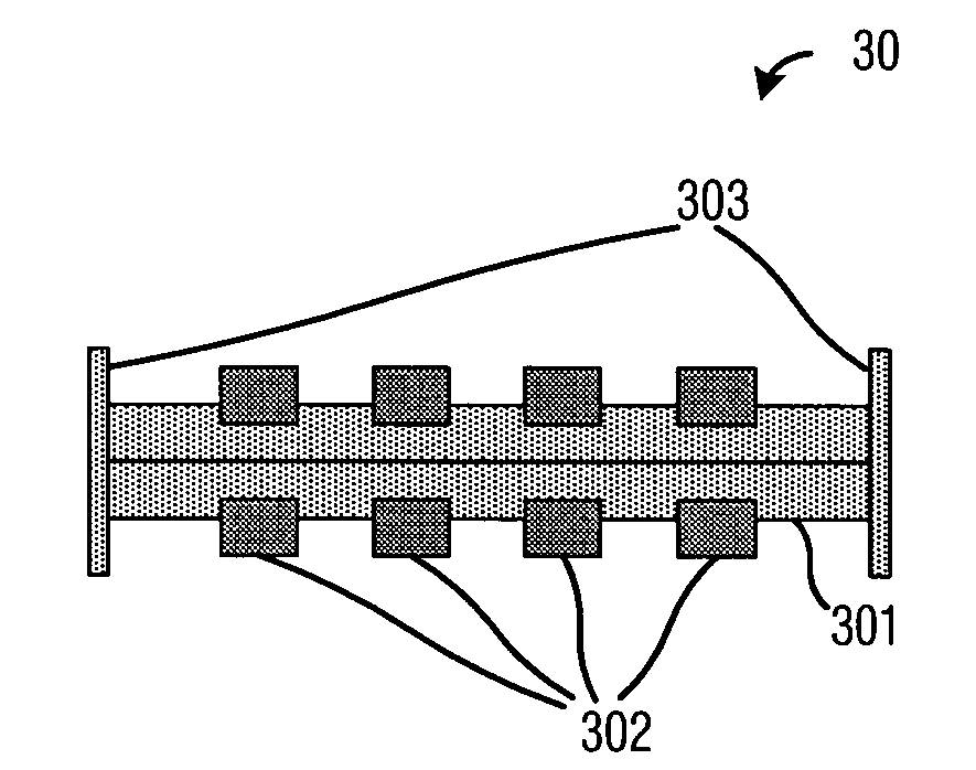
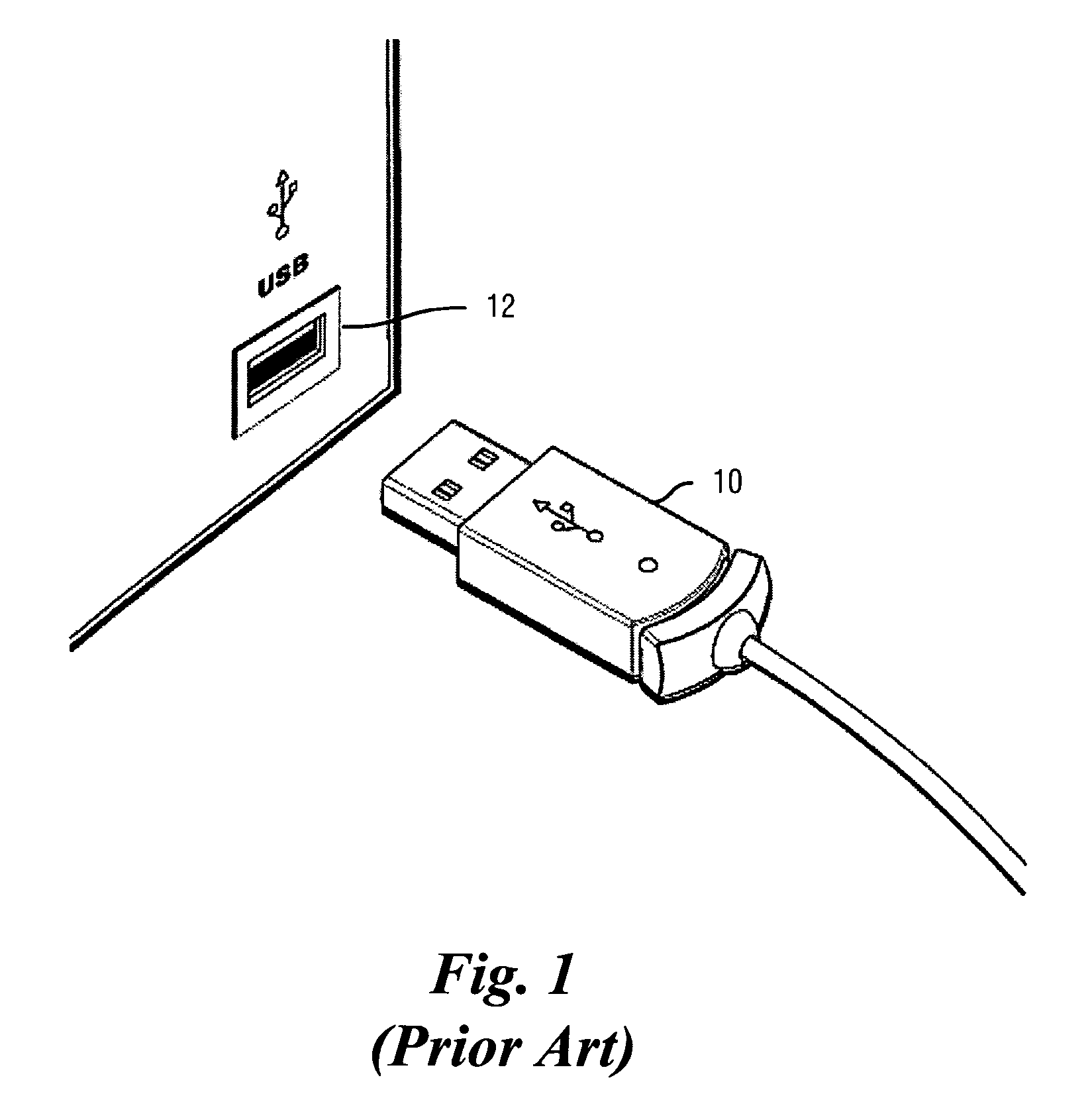
[0036]The preferred embodiment of the present invention is an improvement of existing USB series “A” plugs. This improvement is ach...


PUM


Abstract

An electrical connector, for example a connector that will operate with the Universal Serial Bus, is disclosed. In some embodiments, the connector includes none, one, or several tongue board, tongue tip, electrical contact, housing shell, insulating strip on the inner lining of housing shell, protective edge. A connector integral to a printed circuit board is also disclosed. Other embodiments are disclosed.

Description

[0001]This application claims the benefit of U.S. Provisional Application No. 60 / 490,413, filed on Jul. 28, 2003, entitled Electrical Connector, which application is hereby incorporated herein by reference.TECHNICAL FIELD[0002]The present invention relates to an electrical connector, and more particularly to a Universal Serial Bus (USB) connector.BACKGROUND[0003]In many situations, computers are connected to peripherals or electronic appliances using wire connections. One type of wire connection is the Universal Serial Bus (hereafter USB) cable. A USB cable may be used to electrically connect a computer with peripherals and other electronic appliances. Examples of computer peripherals are input devices such as a mouse and a keyboard, output devices such as printers, and input / output devices such as external hard drives and flash memory drives. Examples of electronic appliances are digital cameras, PDAs, and MP3 players.[0004]In the late 1990's the USB standard became the preferred c...

Claims


Application Information

Patent Timeline
Patent Type & Authority Patents(United States)
IPC IPC(8): H01R24/00H01R12/18H01R13/64H01R33/00H05K1/11
CPCH01R27/00H05K1/117H01R12/721H01R24/62H01R13/6315H05K2201/09145H05K2203/1572H05K2203/168H01R2107/00H01R33/00H05K1/11H01R12/71
Inventor HARKABI, DANELAZAR, GIDONWEINGARTEN, NEHEMIAH
Owner SANDISK TECH LLC
Why Eureka
Try Eureka