

Range image sensor
a range image and sensor technology, applied in the field of range image sensors, can solve the problems of inconvenient devices for such purposes, easy saturation of light detecting elements, and long comparative time taken, so as to reduce the quantity of light received, prevent saturation of light detecting elements, and secure the reliability of distance values obtained
- Summary
- Abstract
- Description
- Claims
- Application Information
AI Technical Summary
Benefits of technology
Problems solved by technology
Method used
Image

Examples
first embodiment
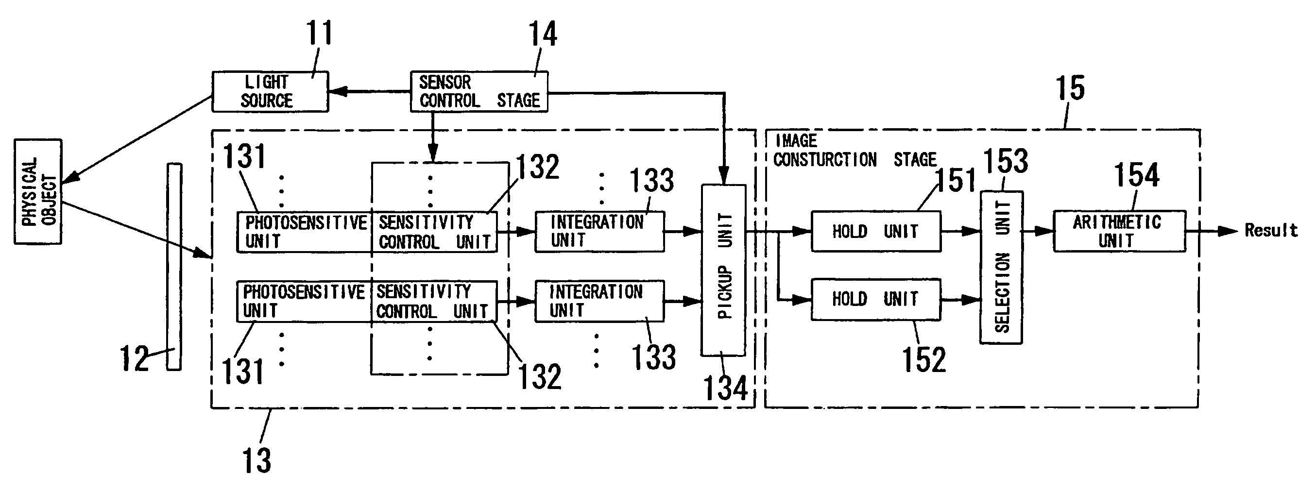
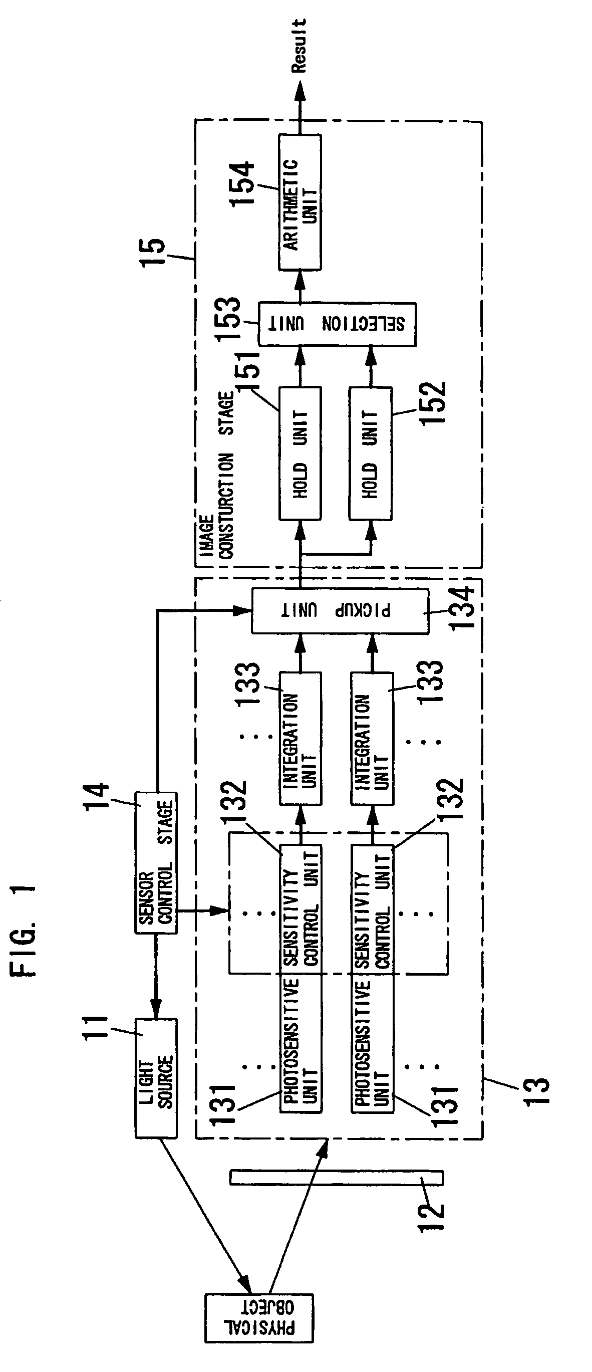
[0037]FIG. 1 shows a range image sensor of a first embodiment according to the present invention. The sensor comprises a light source 11, an optical system 12, a light detecting element 13, a sensor control stage 14 and an image construction stage 15.
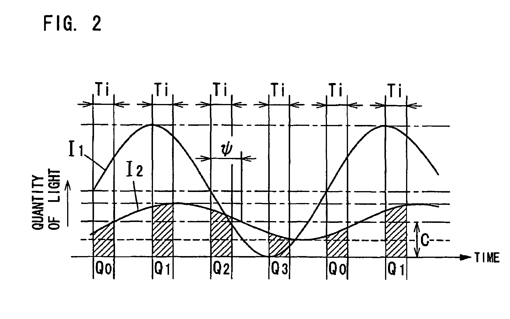
[0038]The light source 11 is constructed with, for example, a LED array arranged on a plane, a semiconductor laser and a divergent lens, or the like, in order to provide enough intensity of light. The source 11 as shown in FIG. 2 modulates intensity I1 of light according to a modulation signal of a specific frequency from the sensor control stage 14 to emit sinusoidal intensity-modulated light toward an object space. However, not limited to this, intensity waveform of the intensity modulated light may be a shape such as a triangular wave, saw tooth wave or the like. Also, the source 11 may comprise an infrared LED array, an infrared semiconductor laser and a divergent lens, or the like.
[0039]The optical system 12 is a receiving optical ...
second embodiment
[0063]FIGS. 5A and 5B show operation of a range image sensor of a second embodiment according to the present invention. In the range image sensor of the second embodiment, two neighboring photosensitive units 231 and 231 along the vertical direction are used as one pixel. Also, overflow drain is provided at every pixel.
[0064]If a photosensitive unit generates the electric charges corresponding to Q0–Q3, resolution with respect to line-of-sight direction becomes high. But the problem of time difference is occurred because at least the specific detection period is required for each of electric charges corresponding to Q0–Q3. Inversely, if four photosensitive units respectively generate the electric charges corresponding to Q0–Q3, it is possible to pick up the electric charges corresponding to Q0–Q3 in synchronization with at least the specific detection period and therefore the time difference become small. However, the resolution with respect to line-of-sight direction becomes low.
[0...
third embodiment
[0077]In a third embodiment according to the present invention, when the specific detection period is not selected or a first specific detection period as the specific detection period is the short detection period shorter than prescribed length, the image construction stage selects a second specific detection period out of the different detection periods at every two phases of the one set of phases with respect to a specific image element for which the specific detection period is not selected or the short detection period is selected.
[0078]In the example of FIG. 7, when a value of each electric charge in the long detection period TL1 (Q0, Q2) is smaller than a value (e.g., saturation threshold value) predetermined based on the saturation level of the light detecting element and also a value of each electric charge in the long detection period TL2 (Q1, Q3) is larger than the saturation threshold value, the specific detection period is not selected or the short detection is selected...
PUM
 Abstract
Description
Claims
Application Information