Lane marker recognition method

a recognition method and technology of lane markers, applied in the direction of vehicular safety arrangements, process and machine control, navigation instruments, etc., can solve the problems of unable to recognize road studs, unable to properly detect white lines, and unable to properly recognize white lines. achieve the effect of stably recognizing

Active Publication Date: 2008-04-22
HITACHI ASTEMO LTD
View PDF25 Cites 62 Cited by
  • Summary
  • Abstract
  • Description
  • Claims
  • Application Information

AI Technical Summary

Benefits of technology

[0013]It is therefore an object of the invention to provide an algorithm that is capable of stably recognizing a lane marker being composed of white lines or road studs without having to discriminate the type of the lane marker.

Problems solved by technology

This hampers proper detection of the shadowed portion of the white line by this approach.
There is still another problem, in which, if the threshold value is set at the luminance level that allows the approach to detect the shadowed portion of the white line, this causes the approach to detect also areas other than the white line.
There is, however, a problem inherent in this technique.
That is, if image conditions change due to weather or shadow, the technique is no longer able to detect the white line properly.
While being capable of extracting edges of the white line stably, the technique using the edge extraction is, however, likely extracts extra edge components on the road, such as a preceding vehicle and a rut.
Thus, it is unable to recognize road studs.
However, the size of the road stud on the image is generally small and the image of the road stud is highly susceptible to noise.
This is a major obstacle to a stabilized recognition rate.
This means that correct recognition cannot be made if the type of the lane marker is incorrectly identified even with excellent algorithms provided for both the white lines and road studs.

Method used


Image

  • Lane marker recognition method
  • Lane marker recognition method
  • Lane marker recognition method

Examples


Embodiment Construction

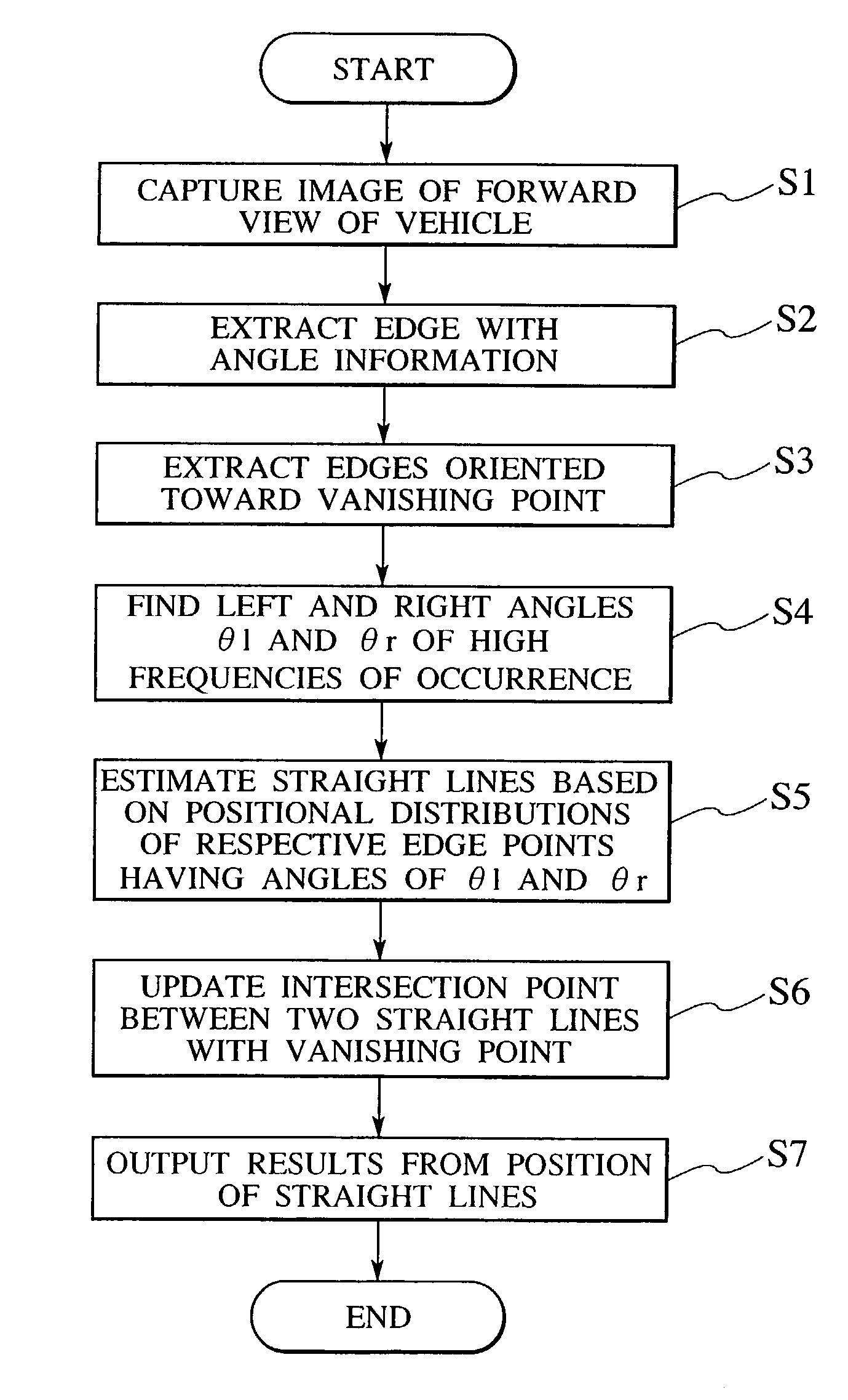
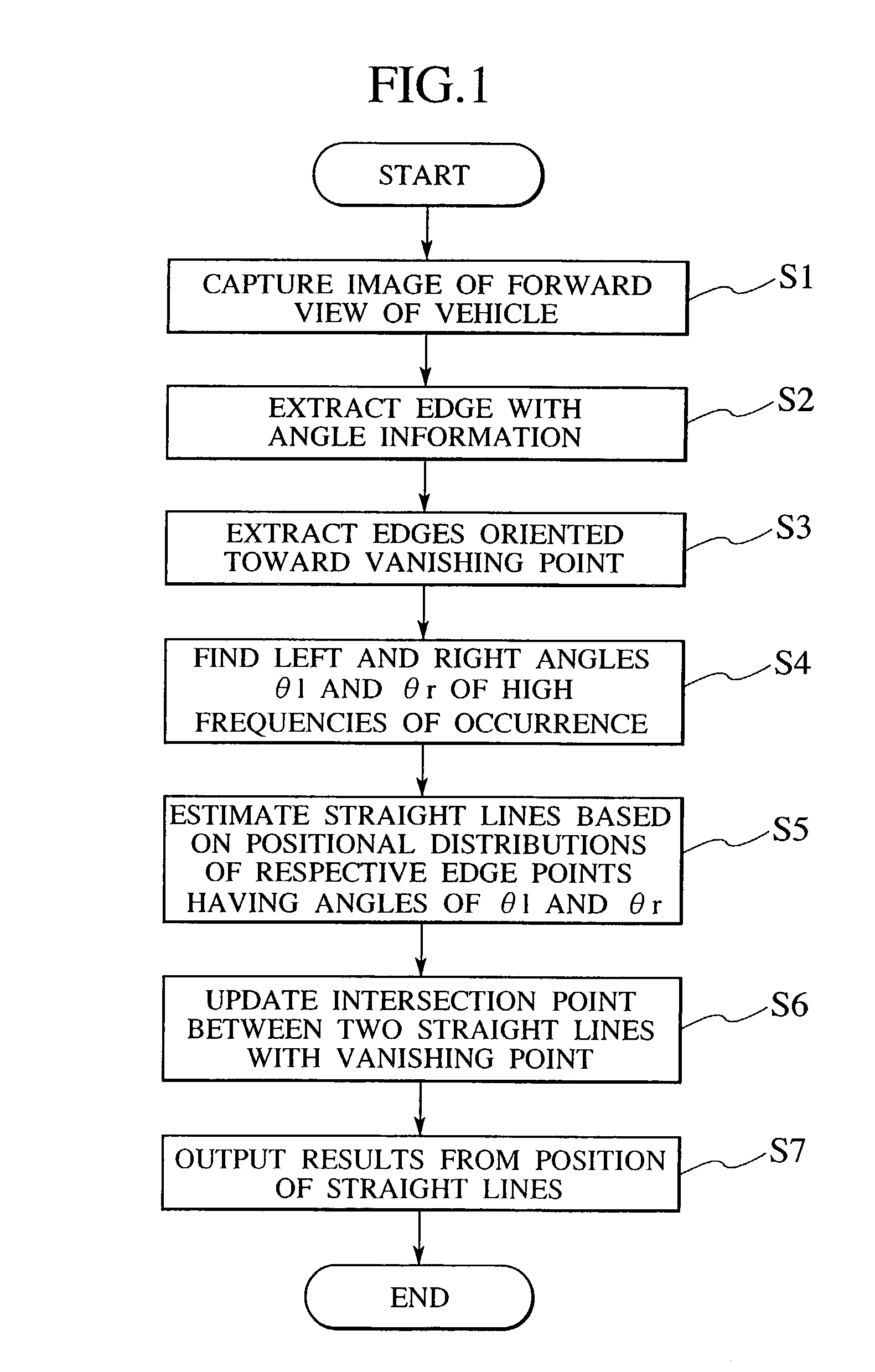
[0031]FIG. 1 shows a processing flow of the lane marker recognition method according to the present invention.

[0032]A lane marker recognition method according to one embodiment of the present invention includes the following steps: a vehicle forward image capturing step (step S1), or an image inputting step of inputting an image including a lane marker; an edge-with-angle-information extracting step (step S2) of taking a luminance change point of the image input through the vehicle forward image capturing step S1 as an edge and calculating an angle of orientation of the edge; an edge selecting step (step S3) of selecting edge points that are oriented toward a vanishing point of the road from the position and orientation angle of the edge point; lane marker position estimating steps (steps S4 to S5) of analyzing a distribution of positions of edge points aligned toward the vanishing point to determine the edge point of the lane marker; a step (step S6) of updating information about t...


PUM


Abstract

A lane marker recognition method comprises the steps of inputting an image including a lane marker, extracting luminance change points in the image, and estimating the position of the lane marker using the extracted edge points. The edge extracting step includes calculating an angle of orientation of each of the edges and the lane marker position estimating step includes extracting edge points that are oriented toward a vanishing point of a road, from among the edge points extracted in the edge extracting step.

Description

BACKGROUND OF THE INVENTION[0001]The present invention relates to a lane marker recognition method that uses road surface information obtained through a camera or other input means to recognize through image processing a vehicle running lane marker, and an apparatus using the same.[0002]A technique has conventionally been proposed in which image processing is employed to recognize a white line or other lane marker placed on a road so as to give a driver a warning if his or her vehicle deviates from a cruising lane. Another technique proposed uses a result of lane marker recognition for steering control of the vehicle.[0003]To recognize a white line through image processing, a common conventional approach sets a threshold value for luminance of an image so as to binarize the image, thereby recognizing a portion with a high luminance value as the white line. This approach uses a principle, in which, since the white line has a higher lightness than a surrounding road area, it according...

Claims


Application Information

Patent Timeline
Patent Type & Authority Patents(United States)
IPC IPC(8): G06K9/00G06F19/00G06K9/48G06K9/66H04N7/00B60R21/00G06T1/00G06T5/00G06T7/00G06T7/60G08G1/16
CPCG06K9/00798G06T7/0042G06T7/0083G06T2207/10016G06T2207/30256G06T7/73G06T7/12G06V20/588
Inventor OTSUKA, YUJIMURAMATSU, SHOJITAKENAGA, HIROSHITAKEZAKI, JIROMONJI, TATSUHIKO
Owner HITACHI ASTEMO LTD
Why Eureka
Try Eureka