Wide-frequency-range television tuner

a television tuner and wide-frequency technology, applied in the field of television tuners, can solve the problems of unstable low tuning voltage and complicated structure of tuning circuit, and achieve the effects of increasing the voltage of the varactor diode, extending the range of received frequencies, and increasing the voltage of the anode of the varactor diod

Inactive Publication Date: 2008-04-22
ALPS ALPINE CO LTD
View PDF8 Cites 2 Cited by
  • Summary
  • Abstract
  • Description
  • Claims
  • Application Information

AI Technical Summary

Benefits of technology

[0022]According to the first aspect of the present invention, a television tuner includes a tuning circuit for tuning a television signal. The tuning circuit includes a first varactor diode for changing a tuning frequency. The television tuner further includes a mixer for converting a television signal output from the tuning circuit to an intermediate frequency signal, an oscillator for supplying a local oscillating signal to the mixer, and a PLL circuit for outputting a tuning voltage for tuning the television signal. The oscillator includes a second varactor diode for changing an oscillating frequency. In the television tuner, the tuning voltage is applied to cathodes of the first varactor diode and the second varactor diode, and voltages of anodes of the first varactor diode and the second varactor diode are higher at a time of receiving the television signal whose frequency is lower than or equal to a predetermined frequency than at a time of receiving a television signal whose frequency is higher than the predetermined frequency. Consequently, the tuning voltage can be increased when receiving a television signal having a frequency less than or equal to the predetermined frequency. As a result, the range of received frequencies can be expanded without using an unstable, low tuning voltage.

Problems solved by technology

As described above, known television tuners increase the received frequency range by providing a switching diode in a tuning circuit in order to switch bands, and therefore, the structure of the tuning circuit becomes complicated.
However, since the tuning voltage is output from a PLL (phase-locked loop) circuit, the low tuning voltage is not stable, which is a problem.

Method used


Image

  • Wide-frequency-range television tuner
  • Wide-frequency-range television tuner
  • Wide-frequency-range television tuner

Examples


Embodiment Construction

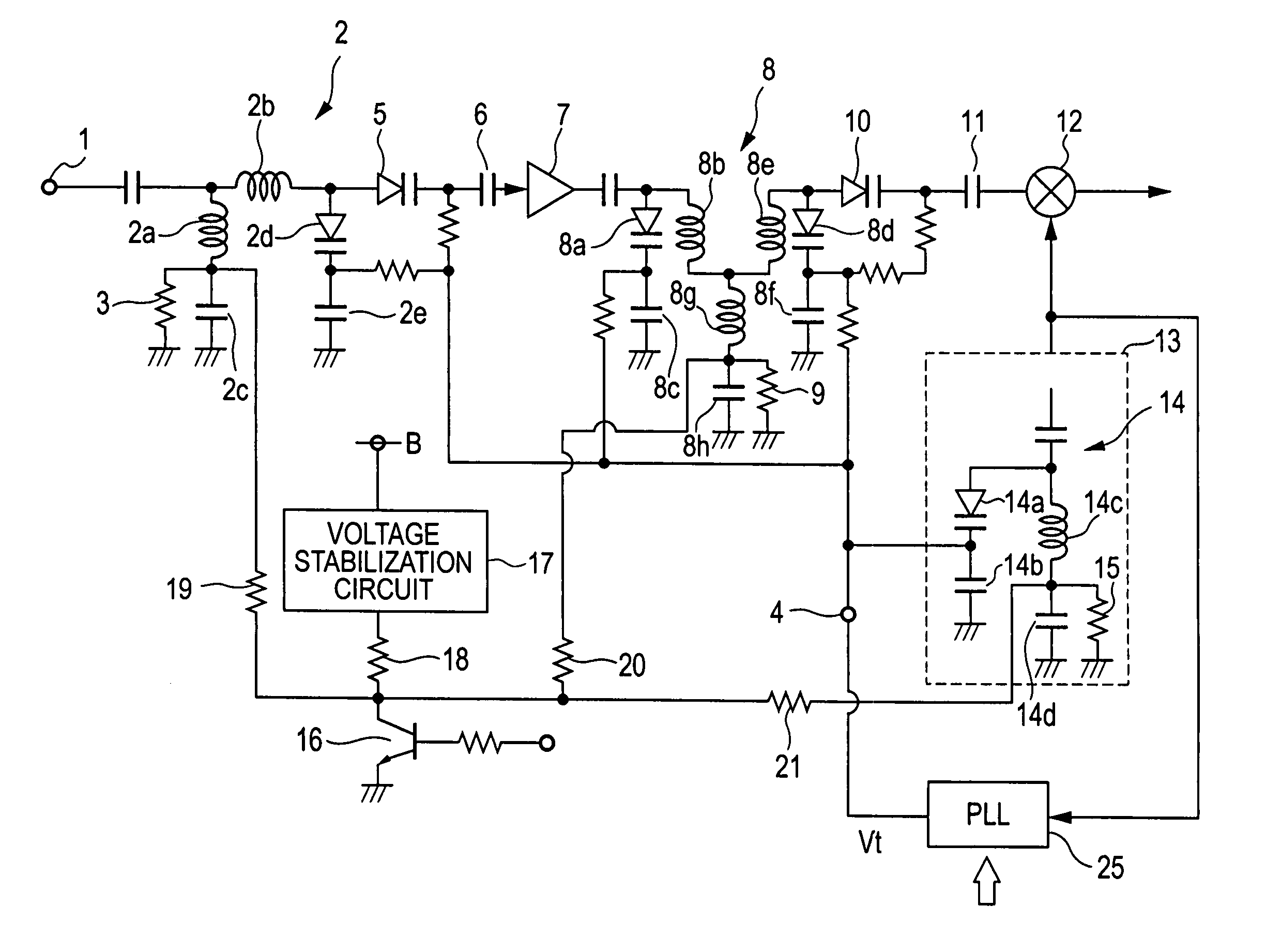
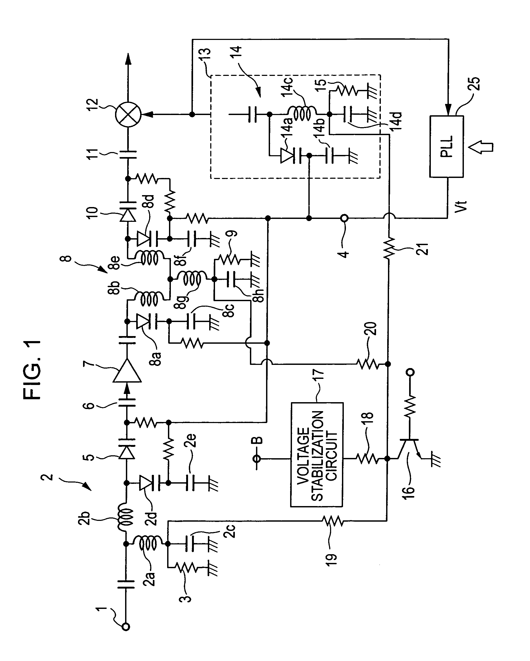
[0030]FIG. 1 is a circuit diagram of a television tuner according to an embodiment of the present invention. For example, an input terminal 1 receives television signals in a VHF broadcast band according to the standard in the United States (the low band covers the frequency range of 55.25 MHz to 83.25 MHz and the high band covers the frequency range of 175.25 MHz to 211.25 MHz).

[0031]An input tuning circuit 2 is connected to the input terminal 1. The input tuning circuit 2 is a tuning circuit that does not carry out band switching. The input tuning circuit 2 includes an inductance element 2a, an inductance element 2b connected in series to the inductance element 2a, a capacitor 2c which connects an end of the inductance element 2a to ground, a first varactor diode 2d whose anode is connected to the inductance element 2b, and a capacitor 2e which connects a cathode of the first varactor diode 2d to ground. A connection point between the inductance element 2a and the capacitor 2c is ...


PUM


Abstract

A television tuner includes a tuning circuit having two first varactor diodes for changing a tuning frequency, a mixer for converting a television signal to an intermediate frequency signal, an oscillator having a second varactor diode, and a PLL circuit for outputting a tuning voltage for tuning the television signal. The tuning voltage is applied to cathodes of the first varactor diodes and the second varactor diode, and voltages of anodes of the first varactor diodes and the second varactor diode are higher at a time of receiving the television signal whose frequency is lower than or equal to a predetermined frequency than at a time of receiving a television signal whose frequency is higher than the predetermined frequency.

Description

[0001]This application claims the benefit of priority to Japanese Patent Application No. 2004-003660 filed on Jun. 23, 2004, herein incorporated by reference.BACKGROUND OF THE INVENTION[0002]1. Field of the Invention[0003]The present invention relates to a television tuner.[0004]2. Description of the Related Art[0005]A known television tuner will be described next with reference to FIG. 4. As shown in FIG. 4, an interstage double-tuned circuit 53 (hereinafter simply referred to as a “double-tuned circuit”) is provided between a high-frequency amplifier 51 and a mixer 52. A primary tuning circuit 53a includes a high-band tuning coil 54, a low-band tuning coil 55 connected in series to one end of the high-band tuning coil 54, and a varactor diode 56 connected in parallel to these tuning coils 54 and 55. An anode of the varactor diode 56 is connected to ground. A cathode of the varactor diode 56 is connected to the other end of the high-band tuning coil 54 via a direct-current blocking...

Claims


Application Information

Patent Timeline
Patent Type & Authority Patents(United States)
IPC IPC(8): H04B7/00H03J3/18H03J3/32H04B1/18
CPCH03J3/185H03J3/32H03J2200/36H03J2200/37H03J2200/38
Inventor YAMAMOTO, MASAKI
Owner ALPS ALPINE CO LTD
Why Eureka
Try Eureka