Exhaust gas throttle for divided turbine housing turbocharger

a turbocharger and exhaust gas technology, applied in the direction of combustion engines, charge feed systems, non-fuel substance addition to fuel, etc., can solve the problems of complex and costly internal vane assemblies of current vgt designs

Active Publication Date: 2008-04-29
INT ENGINE INTPROP CO LLC
View PDF12 Cites 48 Cited by
  • Summary
  • Abstract
  • Description
  • Claims
  • Application Information

AI Technical Summary

Problems solved by technology

Current VGT designs use complicated and costly ...

Method used


Image

  • Exhaust gas throttle for divided turbine housing turbocharger
  • Exhaust gas throttle for divided turbine housing turbocharger
  • Exhaust gas throttle for divided turbine housing turbocharger

Examples


Embodiment Construction

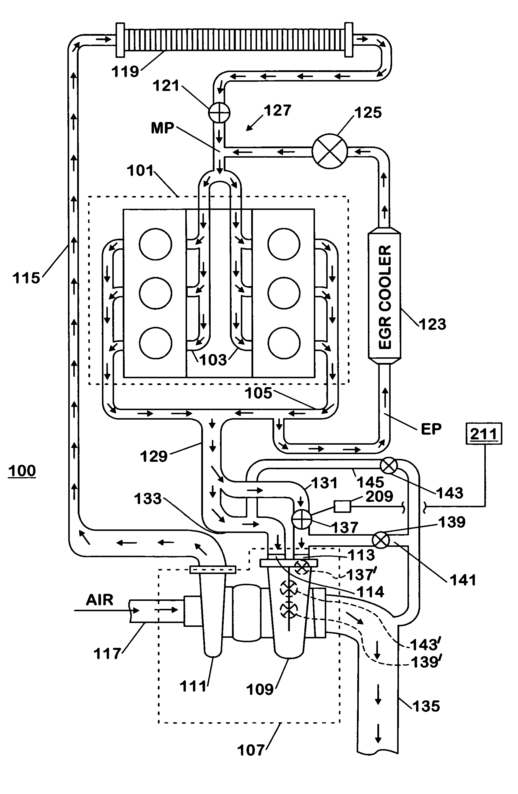
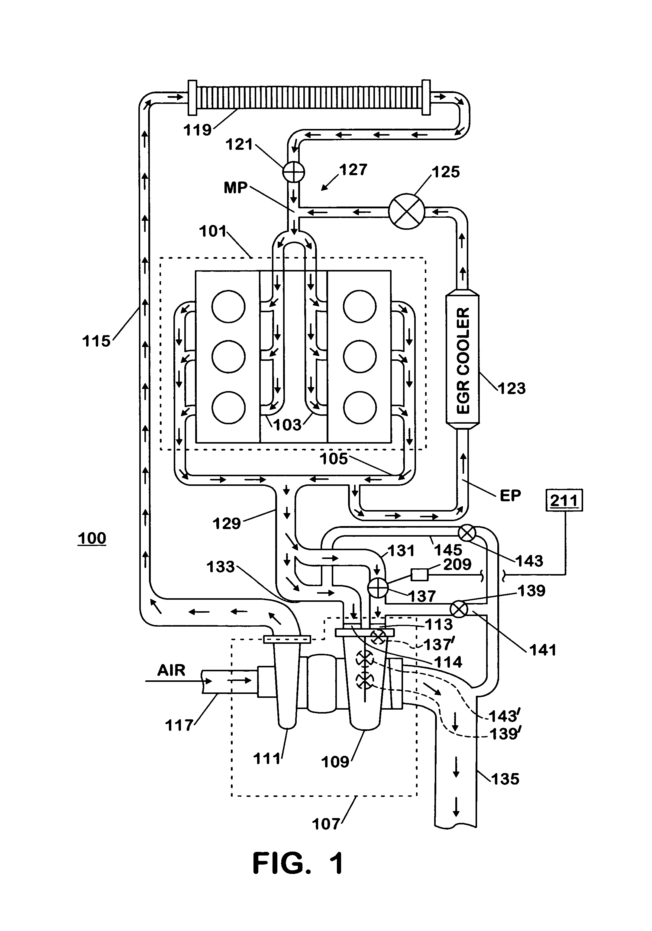
[0008]The following describes an apparatus for and method of operating an internal combustion engine with a free-flow turbocharger in place of a variable geometry turbocharger (VGT), while maintaining a desirable capability of controlling exhaust pressure of the engine in addition to improving a transient response of the engine. An engine 100 is shown in FIG. 1. The engine 100 has a block 101 that includes a plurality of cylinders. The cylinders in the block 101 are fluidly connected to an intake system 103 and to an exhaust system 105. A turbocharger 107 includes a turbine 109. The turbine 109 may be a free-flow type turbine having a divided housing. The turbine 109 may have a first turbine inlet port 113, and a second turbine inlet port 114 connected to the exhaust system 105. The turbocharger 107 may additionally include a compressor 111 connected to the intake system 103 through an inlet air passage 115.

[0009]During operation of the engine 100, air may enter the compressor 111 t...


PUM


Abstract

A turbocharger (107) for an internal combustion engine (100) includes a turbine having a divided turbine housing (109). A first inlet port (113) may be connected to a first volute that is formed in the turbine housing (109), and a second inlet port (114) connected to a second volute that is formed in the turbine housing (109). A center housing may be connected to the turbine housing (109), and a compressor (111) may be connected to the center housing. An exhaust gas valve (137) is in fluid communication with the first inlet port (113) and arranged to at least partially constrict a flow of exhaust gas from entering the first inlet port (113) of the turbine (109), but not constrict the flow of exhaust gas from entering the second inlet port (114).

Description

FIELD OF THE INVENTION[0001]This invention relates to internal combustion engines, including but not limited to control and operation of a turbocharger for an internal combustion engine.BACKGROUND OF THE INVENTION[0002]Many modern engines use variable geometry turbines (VGT) as part of turbocharger systems for refined engine control, transient response, and lower emissions. A function of a VGT depends on a position of internal vanes that direct a flow of exhaust gas to a turbine wheel. These internal vanes are also capable of modulating a pressure drop across the VGT, effectively controlling a pressure of the exhaust gas upstream of the VGT. Control of exhaust pressure in an engine is advantageous to engines having exhaust gas recirculation systems, because a pressure difference between an intake system and the exhaust system may be controlled to augment the flow of exhaust gas to be recirculated.[0003]Current VGT designs use complicated and costly internal vane assemblies that have...

Claims


Application Information

Patent Timeline
IPC IPC(8): F02D23/00
CPCF02B37/025F02B37/18F02B37/22F02D9/04F02D23/00F02B29/0406F02M25/0707F02M25/0727F02M25/0749Y02T10/144F02M26/05F02M26/23F02M26/43Y02T10/12
Inventor DICKERSON, STEVEN J.
Owner INT ENGINE INTPROP CO LLC
Why Eureka
Try Eureka